TP301 – Operation, Maintenance and Instructions Manual
2.2
Power Supply
The transmitter is powered with 12 to 45 Vdc using the signal line (2-wire system). The transmitter
quiescent consumption is 3.6 mA; during operation, consumption may be as high as 21 mA, depending
on the measurement and sensor status. If configured for low signal failure, the TP301 shows 3.6 mA
indication if configured for high signal failure, it shows 21 mA indication;,3.8 mA in the case of low
saturation; 20.5 mA in the case of high saturation and measurements proportional to the range position
between 4 mA and 20 mA. 4 mA corresponds to 0% of the working range and 20 mA to100 % of the
range.
Display Controller
Receives data from the CPU and drives the liquid crystal display (LCD).
Local Adjustment
Local adjustment is provided by means of two magnetically actuated switches with no external electric
or mechanical contact, by using a magnetic tool..
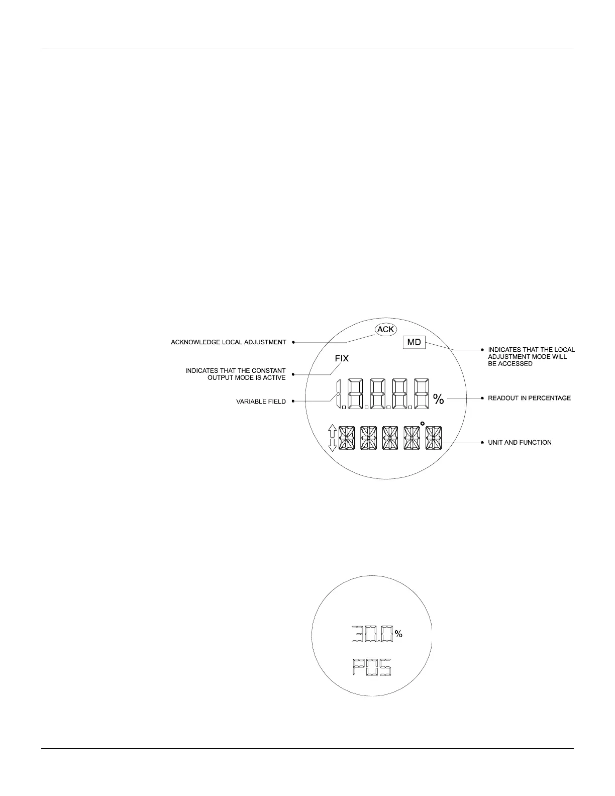
Local Indicator
The local indicator is used for signaling and operation in local adjustment. During normal operation, the
TP301 remains in the monitoring mode and the display indicates the valve position, either as a
percentage or as a current readout,according to the end-user configuration. The magnetic tool activates
the local programming mode, by inserting it in orifice Z on the electronic housing.
The possible configuration and monitoring operation are shown on figure 2.2. When first powered, the
TP301 initializes, by showing model TP301 and its software version (X.XX) on the display.
Figure 2.2 - Local Indicator
Monitoring
During normal operation, the TP301 remains in the monitoring mode. The figure 2.3 shows the
positioning on the display. The display simultaneously shows the readout and other information chosen.
Normal displaying is interrupted when the magnetic tool is placed in orifice Z (Local Adjustment),
starting the programming and local adjustment mode. The figure 3.1 shows the result of tool insertion in
orifices Z and S, which inform, respectively, movement and actuation of the selected options.
Figure 2.3 – Typical Indicator