HGM4100LT GENSET CONTROLLER USER MANUAL
HGM4100LT Genset Controller 2019-01-28 Version1.0 Page 19 of 48
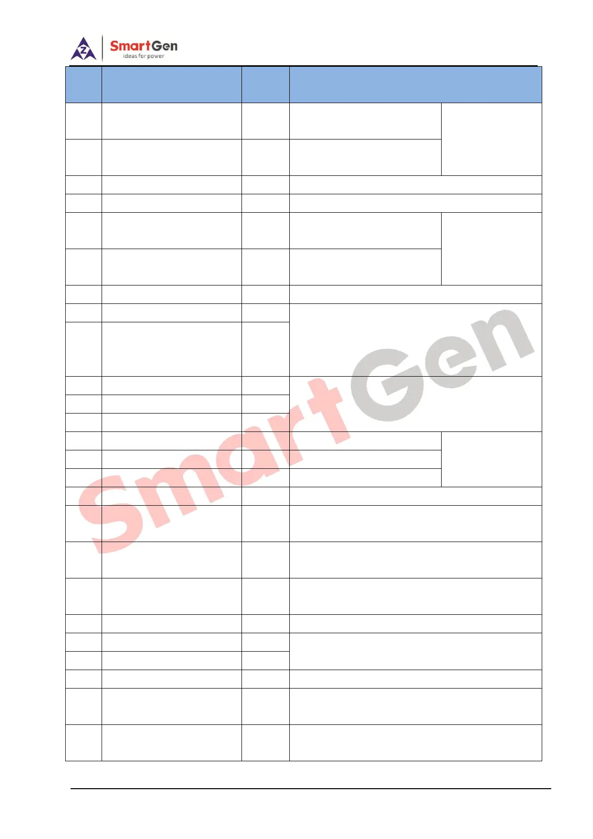
B+ output is supplied by
terminal 2 with rated 1A.
B+ output is supplied by
terminal 2 with rated 1A.
Used as liquid level sensor or digital input port 4;
Used as programmable sensor or digital input port 5;
Connected with water/cylinder
temperature resistor sensor;
For setting items
please refer to
Table 10.
Oil pressure sensor input
Connected with oil pressure
resistor sensor.
COM ground-connected port
Internally connected with B-;
Connected with speed sensor; Shielding line is
recommended.
Speed sensor input;
connected with battery
cathode inside controller;
Impedance-120Ω shielding wire is recommended;
One end is ground-connected.
Ground-connected is active (B-);
For setting items
please refer to
Table 9.
Ground-connected is active (B-);
Ground-connected is active (B-);
Internally connected with B-;
Genset U-phase voltage
monitoring input
Connected to U-phase of genset output (2A fuse
recommended);
Genset V-phase voltage
monitoring input
Connected to V-phase of genset output (2A fuse
recommended);
Genset W-phase voltage
monitoring input
Connected to W-phase of genset output (2A fuse
recommended);
Connected to N-line of genset output;
Connected with CAN BUS if CAN BUS exists;
shielding wire is recommended.
CTA-phasemonitoring input
Externally connected to CT secondary coil (5A
rated);
CT B-phase monitoring input
Externally connected to CT secondary coil (5A
rated);