HGM4100LT GENSET CONTROLLER USER MANUAL
HGM4100LT Genset Controller 2019-01-28 Version1.0 Page 20 of 48
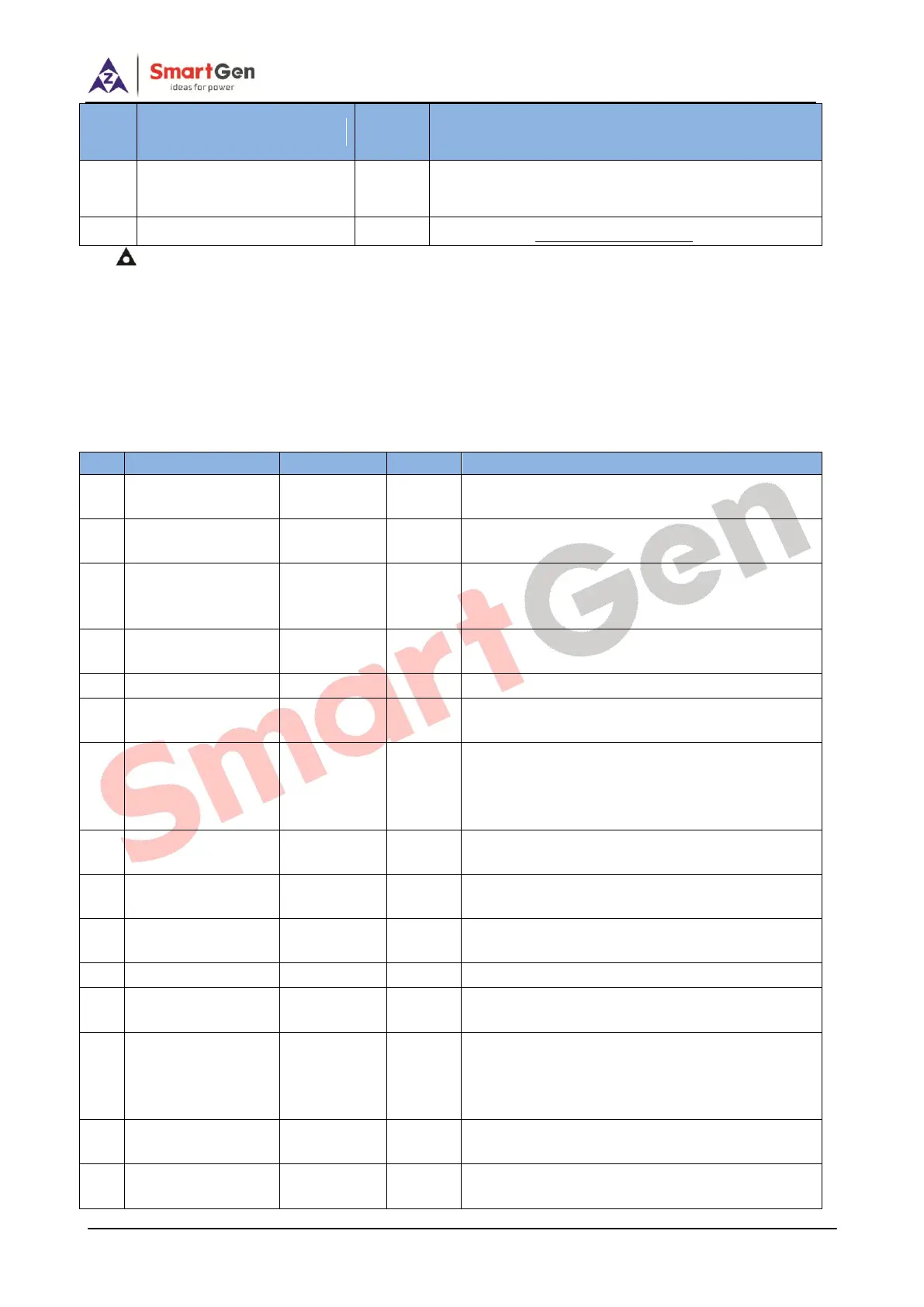
CT C-phase monitoring
input
Externally connected to CT secondary coil (5A
rated);
Reference to Installation Instruction
NOTE: USB ports in controller back panel are programmable parameter ports, and users can directly
configure the controller via PC.
7 SCOPES AND DEFINITIONS OF PROGRAMMABLE PARAMETERS
7.1 CONTENTS AND SCOPES OF PARAMETERS
Table 7 Contents and Scopes of Parameter Settings
From time when remote start signal is active to
the time when the genset starts;
From time when remote start signal is reactive
to time when the genset stops;
The max. crank attempts for start failure; when
it reaches the crank times, the controller shall
send start failure signal.
Power-on time of heater plug before starter is
powered up;
Power-on time of starter every time;
The waiting time before the second power on
when engine fails to start;
During this period, low oil pressure, high
temperature, under speed, under frequency,
under voltage, charge alt failure alarms are all
inactive.
Running time at idling speed when genset
starts;
Warming up time before breaker close and after
high speed running;
Radiating time before genset stop, after it
unloads.
Idle running time when genset stop.
Power-on time for stop coil after genset
unloads;
Time from end of idling speed delay to complete
stop when ETS output time is set “0”; Time from
end of ETS delay to complete stop when ETS
output time is not “0”;
Width of generator close pulse; Continuous
output when it is 0;
Flywheel teeth of engine; which is used for
judging starter disconnection conditions and