HGM4100LT GENSET CONTROLLER USER MANUAL
HGM4100LT Genset Controller 2019-01-28 Version1.0 Page 18 of 48
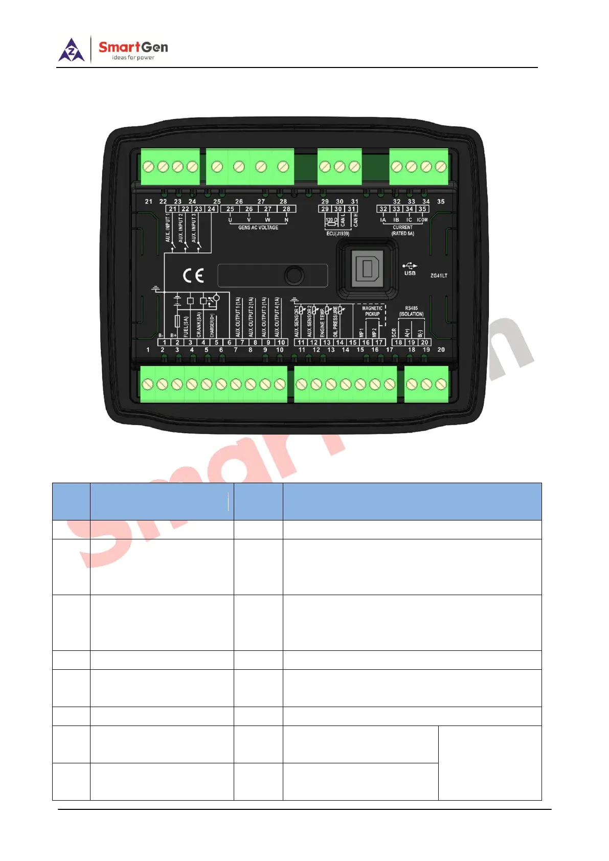
6 WIRING CONNECTION
HGM4100LT controller back panel is as bellows:
Fig.3 HGM4100LT Back Panel
Table 6 Terminal Wiring Connection
Connected with negative of starter battery;
Connected with positive of starter battery; If wire
length is over 30m, it is better to double wires in
parallel; Max. 20A fuse is recommended.
B+ output is supplied by terminal 2 with rated 5A; It
is “programmable relay output 5” in parameter
setting.
B+ output is supplied by terminal 2 with rated 5A.
Connected with charger starter’s terminal D+ (WL);
Let it hang up if there is not the terminal in charger.
COM ground-connected port
Internally connected with B-;
B+ output is supplied by
terminal 2 with rated 1A.
For setting items
please refer to
Table 8.
B+ output is supplied by
terminal 2 with rated 1A.