HRX-OM-W058
Chapter 2 Name and Function of Parts
2.3 Function of Parts HRS-R Series
2.3 Function of Parts
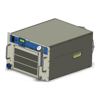
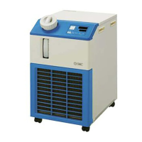
The function of parts is as follows.
Table 2-2 Function of parts
Runs and stops the product and performs settings such as the circulating
fluid temperature.
For details, refer to ’’2.4 Operation display panel’’.
Indicates the circulating fluid level of the tank. For details, refer to ’’3.5 Fill of
circulating fluid’’.
Shows the part number of the product.
For details, refer to ‘’1.4.1 Product Label’’.
Circulating fluid outlet port
The circulating fluid flows out from the outlet port.
Circulating fluid return port
The circulating fluid returns to the return port.
This drain port to drain the circulating fluid out of the tank.
(The plug is connected to standard pump type at the time of shipment. The
ball valve is installed in the high pressure pump type.)
Insert the power cable through the power cable entry and connect to the
terminal block or earth leakage breaker (option B).
Refer to ”3.3.2 Electrical wiring” and “3.3.3 Preparation and wiring of
power supply cable” for details.
Earth leakage breker
(When Earth leakage breker
[Option B] is selected.)
Insert the signal cable through the signal cable entry and connect to the
teminal or D-sub connector for communication.”3.3.5 Wiring of operation
signal output and alarm signal output”, ”3.3.6 RS-485 Communication
wiring”, “3.3.7RS-232C Communication wiring” or refer to the Operation
Manual for communication for details.
Automatic water-fill port
(When automatic fluid filling
[Option J] is selected.)
Piping to the automatic fluid filling port enables easy supply of the circulating
fluid through the built-in solenoid valve.The supply pressure should be in a
range of 0.2 to 0.5MPa.
Overflow port
(When automatic fluid filling
[Option J] is selected.)
This is necessary when automatic fluid filling function.Discharge excess
circulating fluid when the fluid level in the tank rises.
 Loading...


