0
1
123.45 mm
[ ]
[ ]
[ ]
“Normal Mode” for detailed setting
¡Step data setting, parameter
setting, monitoring, teaching,
etc., are displayed in different
windows.
Step data
setting window
Parameter
setting window
Monitoring window
Teaching window
Controller setting software
<When a PC is used>
Main menu screen
Step data
setting screen
Test screen
Monitoring screen
Select “Normal Mode” when detailed setting is required.
<When a TB (teaching box) is used>
Teaching box screen
¡Step data can be set in detail.
¡
Signals and terminal status can be monitored.
¡Parameters can be set.
¡
JOG and constant rate movement, return to origin, test drive, and testing of forced output can be performed.
¡Multiple step data can be
stored in the teaching box and
transferred to the controller.
¡Continuous test drive by up to
5 step data
¡
Each function (step data setting,
test drive, monitoring, etc.) can
be selected from the main menu.
The actuator and controller are provided as a set. (They can be ordered separately as well.)
Confi rm that the combination of the controller and actuator is correct.
<Check the following before use.>
q Check the actuator label for the model number. This number should match that of the controller.
w Check that the Parallel I/O confi guration matches (NPN or PNP).
Controller
q
w
Actuator
q
2
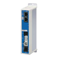
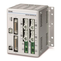
Step Motor Controller JXC Series
Step
Step No.
Parameter
Menu Axis 1
Axis 1
Axis 1
Axis 1
Step No.
Test
Step data
Movement MOD
Test DRV
Out mon
Posn
BUSY
SVRE
SETON
 Loading...


