PTE-100-C PRO
13
REPLACE BLOWN FUSES WITH IDENTICAL ONES ONLY. DAMAGE
RESULTING FROM INCORRECT FUSE REPLACEMENT IS NOT COVERED
BY THE WARRANTY.
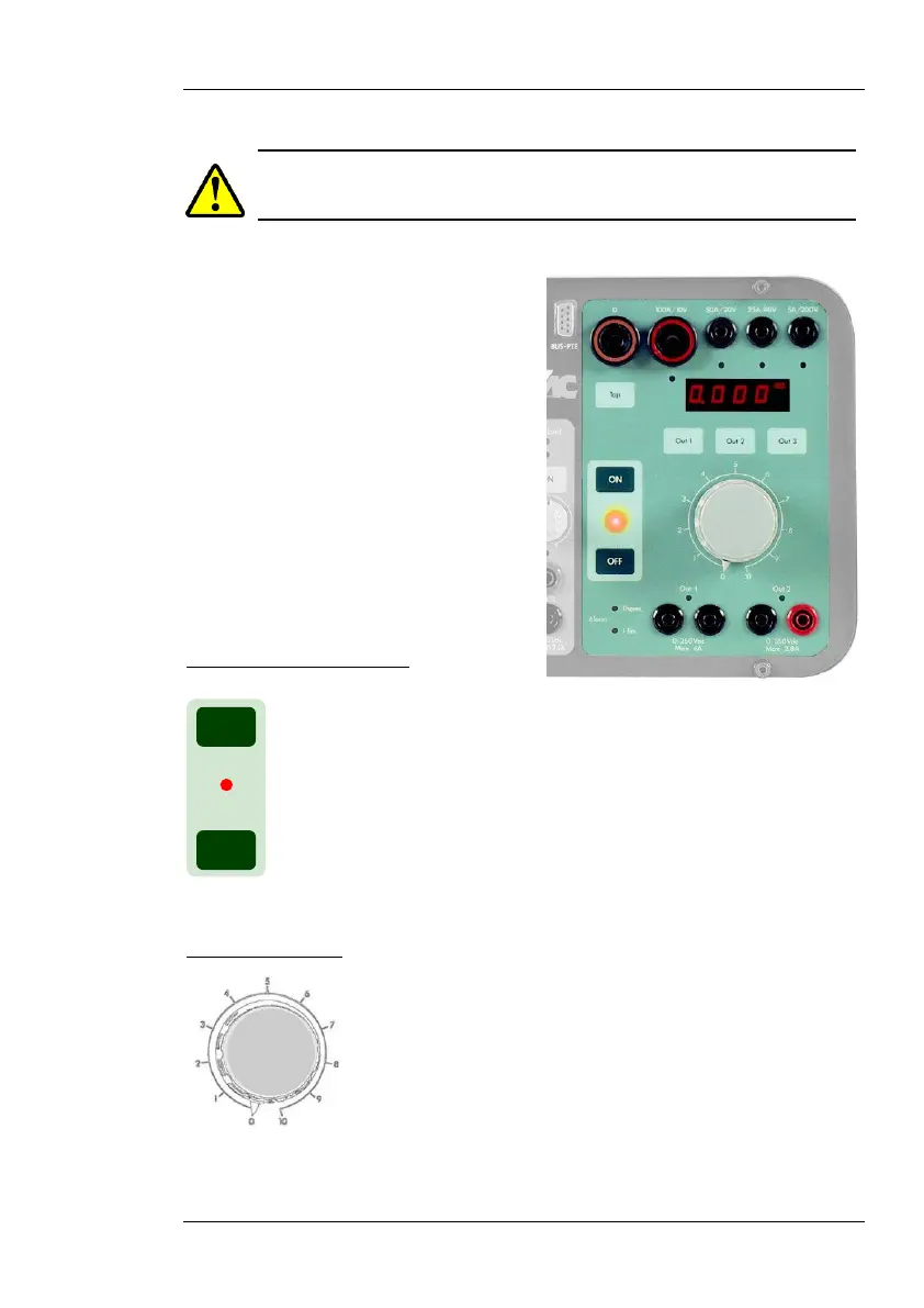
POWER OUTPUT SECTION
This is the right-hand section of the
front panel. It contains the main out-
put control buttons, the regulation
variac, the Display #2, the current
and voltage output taps, the tap selec-
tor, the displayed output selector and
a few associated and alarm LEDs:
Output ON/OFF buttons
These buttons connect and disconnect the main power ouput,
i.e. the current output taps and the Out 1 and Out 2 voltage
taps. A red LED indicates the following output states:
OFF: The output has been intentionally switched off
ON: The output has been intentionally switched on
BLINK: The output has been switched off by the unit. This will
be further explained under the OPERATION section.
Regulation Variac
This knob controls the output level of the current and
voltage power taps. The numerical 0-10 round scale is
provided as a positional reference only. The actual
output level is shown in Display #2 and, at any given
regulator position, its value always depends on the
connected impedance. Regardless of the regulator’s
position, no power will be output when the output control switch is OFF.
Always handle this regulator with care.
ON
OFF
 Loading...

