USER’S MANUAL
20
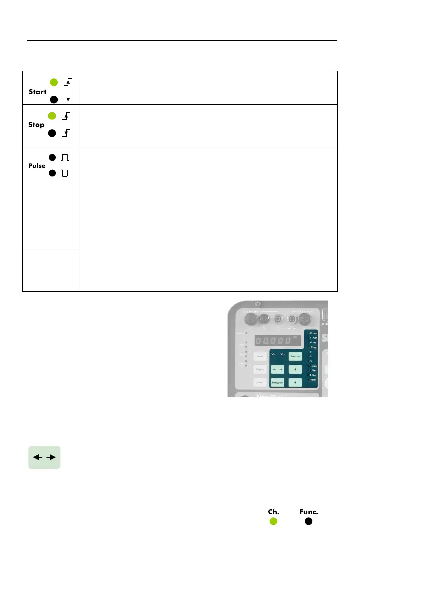
Upper LED: the timer will start w
hen injection is switched on.
Lower LED: the timer will start when injection is switched off.
Upper LED: the timer will stop when the monitor is set to ac-
tive. Lower LED: the timer will stop when the monitor is set to
inactive.
Pulse mode measures the time elapsed between two opposite
monitor events.
Upper LED (positive pulse): The timer will start when a moni-
tor condition appears and will stop when it disappears.
Lower LED (negative pulse): The timer will start when an exist-
ing monitor condition disappears and will stop when it comes
back.
• Monitor
Monitor detection occurs when a contact is closed between
the BLACK/GREEN or a voltage appears between the
BLACK/RED monitor input connectors.
SPECIAL FUNCTIONS
The following buttons provide access to the
special measurement and control functions
grouped in the shaded area underneath
Display #1. These functions are provided to
complement the main unit’s features and to
simplify frequent in-field operations.
Press this button to access or exit the special functions listed be-
low. When done, press it again for normal operation. Two LEDs
labeled Ch. (chrono) and Func. will identify the active operation
mode. When in the special functions mode, Display#1 will tem-
porarily show measurement and setup values
related to each function. Any displayed time
value will be restored when backing up to
normal mode.
 Loading...

