USER’S MANUAL
44
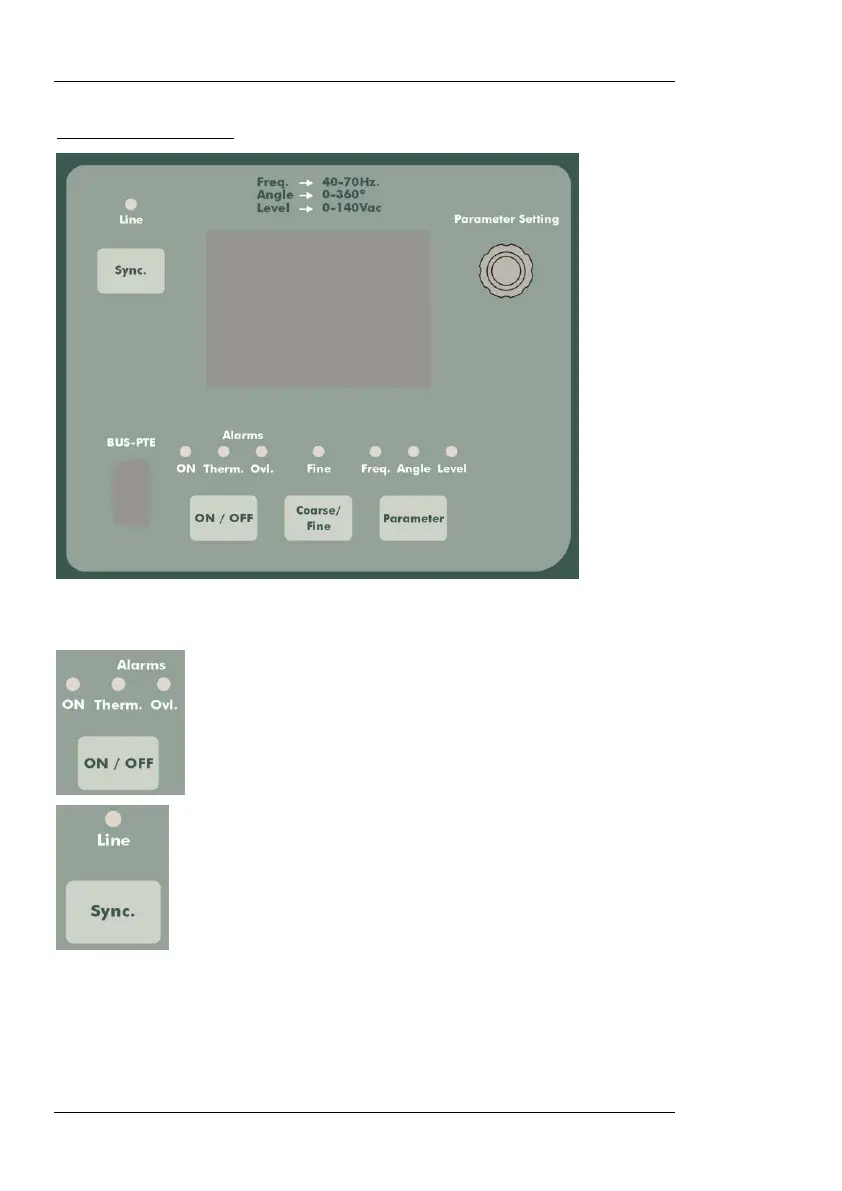
BUTTONS AND LEDS
The PTE-FCN’s output is regulated by means of a single rotary knob and
four control buttons, used as follows:
Press this button to switch the output ON and OFF. The
associated red LED will indicate the present output state.
Press this button to toggle the module’s phase reference
from “Line” (i.e. the PTE-100-C’s 50 or 60-Hz AC supply
line) to its internal wave generator, whose frequency you
can change as described next.
When Line is selected as the synch reference, the LCD
display shows the phase angle between this voltage and
the current being injected by the main PTE-100-C unit.
When Line is deselected, the LCD display shows the ad-
justable output voltage’s frequency, which is generated by
the PTE-FCN module and, therefore, is no longer refer-
enced to the main unit’s current or voltage outputs.
 Loading...

