PTE-100-C PRO
17
AUXILIARY VOLTAGE
Auxiliary Outputs are intended as general purpose vol-
tage supplies, rather than actual power sources. These
outputs are also galvanically isolated from each other
and from the main power supply.
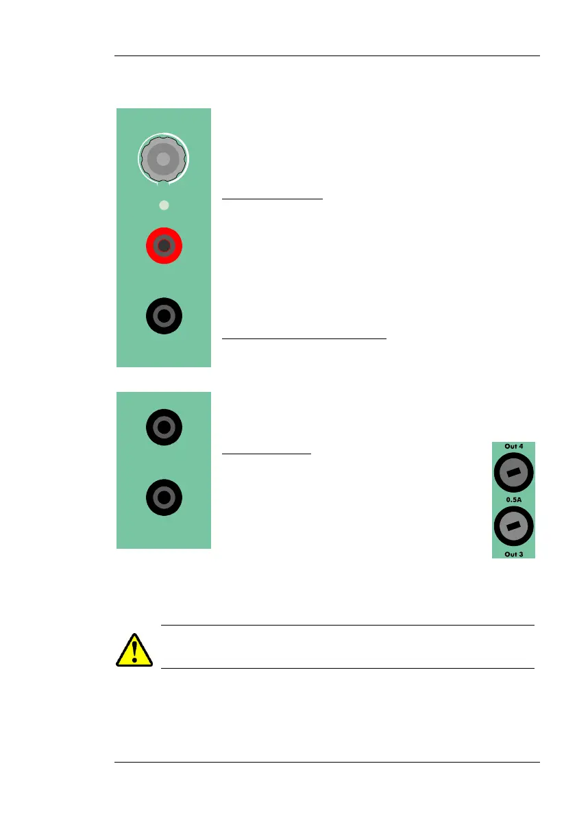
Out 3: 0-250
Out 3 is located on the center section of the front panel.
Polarity of this d. c. output is color-coded in its 4 mm
connectors: black (negative) and red (positive).
Vdc
This auxiliary output has its own regulation knob and an
ON/OFF button with a red LED that will lit when the
output is active.
Out 3’s Automatic Protections
An orange-color LED will blink and the output will be
suspended while Out 3 is short-circuited. In case of over-
heating, the LED will be lit steadily. Both alarms will be
cleared and the output will be automatically resumed
when conditions return to normal.
Out 4: 110 Vac
Out 4, the fixed 110V AC auxiliary output
located next to the AC supply block, is active
whenever the unit is switched on.
Out 3 and Out 4 are protected by two 5x20
mm, 0.5 A fuses located on the left side of
the AC supply block. To open the fuse holder, press and turn
90º anti-clockwise with a small screwdriver.
REPLACE BLOWN FUSES WITH IDENTICAL ONES ONLY. DAMAGE
RESULTING FROM INCORRECT FUSE REPLACEMENT IS NOT COVERED
BY THE WARRANTY
Out 3
0-250 Vdc
Max. 0.25 A
Out 4
0-110 Vac
Max. 0.3 A
 Loading...

