Page 5 - 4 UL25/UL32/UL40
SCHEMATICS
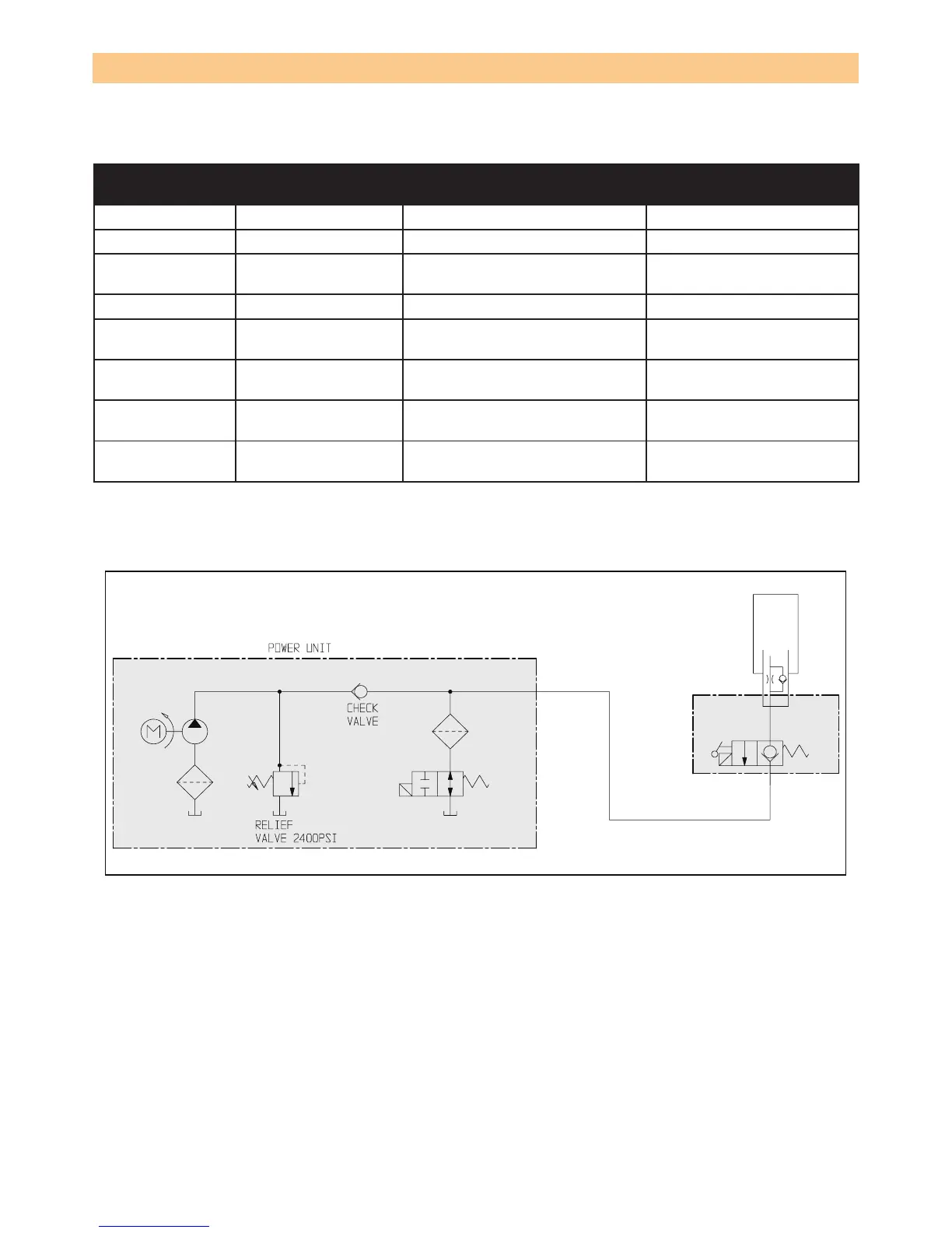
HYDRAULIC SCHEMATIC
REFERENCE
DESIGNATION
NAME FUNCTION LOCATION
CV Check valve Allows ow in one direction Valve block assembly
CYL Cylinder Operates lift On lift assembly
FLT
Filter Separates matter held in sus-
pension from uid.
Inline with pump.
ORF Orice Controls ow out of cylinder Inline with cylinder
P
Pump Supplies hydraulic pressure
to system
Lower power module
RV
Relief valve Limits maximum pressure by
releasing oil
Valve assembly
Lower power module
V1
Valve, 2-way norm.
Open
Stops ow when energized. Valve block assembly
V2
Valve, 2-way norm.
Closed
Allows ow when energized. Lift cylinder assembly.