probe
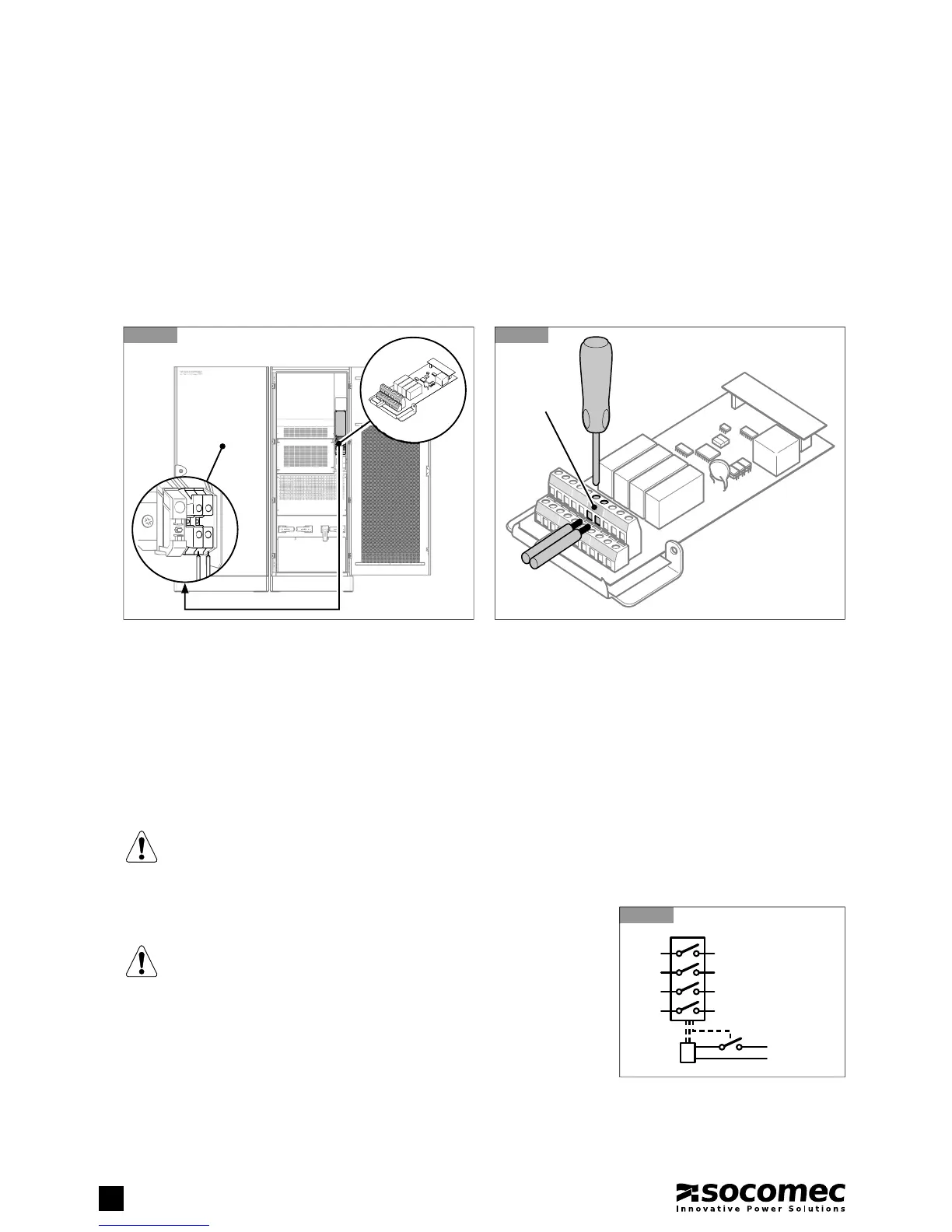
2.6.4. Connecting THE BATTERY CABINET TEMPERATURE PROBE
• SOCOMEC battery cabinets:
- The SOCOMEC battery cabinet comes with a temperature probe which must be connected to the card supplied with the UPS
(fi gure 2.6.4-1).
- Connect the temperature probe as shown in fi gure 2.6.4-2 without cabling distance limits and without the need to observe
polarity.
- In the event of a single UPS with several battery cabinets use a single temperature sensor.
- In the event of parallel UPSs connect the battery cabinet temperature sensors to the cards installed in the related UPSs.
• Other manufacturers battery cabinets:
- Use the specifi c kit available as an option.
- Fix the probe in the battery room or inside the battery cabinet.
- Connect the temperature probe as shown in fi gure 2.6.4-2 without cabling distance limits and without the need to observe polar-
ity, by using a 2x1 mm
2
double insulation cable.
- In the event of a single UPS with several battery cabinets, use a single temperature sensor.
- In the event of parallel UPSs, connect the battery cabinet temperature sensors to the cards installed in the related UPSs.
Note: If you do not intend to use the battery cabinet temperature sensor, go to the MAIN MENU > SLOT OPTIONS > BATTERY
TEMPERATURE PROBE menu, and set the parameter Battery Temperat. Probe as Not Present.
WARNING!
If the Battery Temperat. Probe parameter is set to Not Present, the battery charger will not correct the recharge
voltage as a function of the temperature.
2.6.5. Connecting THE EXTERNAL BACKFEED PROTECTION
To guarantee maximum protection use a 220-240 V release coil with
integrated travel limit contact to pilot the input protection systems (see
section 2.5 Electrical requirements).
If a trip coil without an integrated end-of-travel contact is used, add an
early auxiliary contact as shown in figure 2.6.5-1.
Electrical contact data: 2 A 250 Vac