40
MASTERYS BC 100-120 kVA - Ref.: IOMMASBCXX07-EN 05
7. CONNECTIVITY AND COMMUNICATION OPTIONS
ENVIRONMENTAL confi guration
DIP1: ON - DIP2: ON
IN/OUT Description Filter level
OUT 1 General Alarm 2
OUT 2 Overheating 2
OUT 3 Overload / Loss of redundancy 2
OUT 4 External alarm In2 2
IN 1
(1)
ESD 1
IN 2 External alarm A39 2
IN 3
(2)
External alarm A40 2
POWER SAFE confi guration
DIP1: ON - DIP2: OFF
IN/OUT Description Filter level
OUT 1 General Alarm 2
OUT 2 Power safe plug 1 2
OUT 3 Power safe plug 2 2
OUT 4 Power safe plug 3 2
IN 1
(1)
ESD 1
IN 2 Supply from GenSet 1
IN 3
(2)
Management of energy consuption
1
STANDARD confi guration (default)
DIP1: OFF - DIP2: OFF
IN/OUT Description Filter level
OUT 1 General alarm 2
OUT 2 Battery discharging 3
OUT 3 Battery low or imminent stop 2
OUT 4 UPS on bypass 2
IN 1
(1)
ESD 1
IN 2 Supply from GenSet 1
IN 3
(2)
Insulation controller 2
(1) If the external ESD button is not used always insert a jumper to short circuit input IN 1.
(2) The IN3 input on the ADC card with temperature sensor is for the external battery temperature sensor.
The fi lter level indicates the activation delay: 1 immediate activation (1 second minimum communication time), 2 10 s delay, 3 30 s delay.
SAFETY confi guration
DIP1: OFF - DIP2: ON
IN/OUT Description Filter level
OUT 1 General Alarm 2
OUT 2 ESD activation 1
OUT 3 Battery low or imminent stop 2
OUT 4 ESD activation 1
IN 1
(1)
ESD 1
IN 2 External alarm A39 2
IN 3
(2)
External alarm A40 2
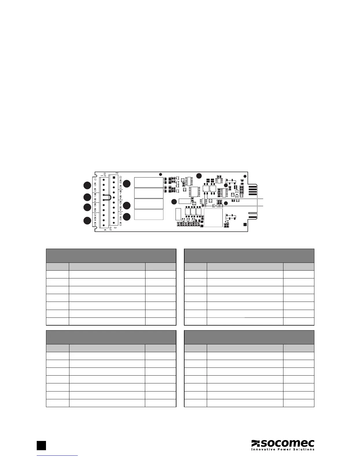
7.2. ADC CARD
To be installed in one of the two slots available, these cards can be used to manage up to four normally closed or normally open
outputs, and up to three digital inputs in confi gurable mode. If more than one ADC card is used simultaneously, the dip switch
confi gurations must be di erent. Secure the card with the appropriate screws.
This card can be confi gured to control up to four outputs that can be set as normally closed or normally open and up to three digital in-
puts. The card is inserted in one of two slots provided. Up to four operating modes can be selected using the two DIP switches 1 or 2.
• Electrical data
- Permitted Nominal current and voltage of NO or NC contacts: 2 A 250 Vac depending on the terminal used.
- Inputs are activated on loop closing.
• Connection of the generator
If your system uses a generator connect the ‘generator set ready’ no-potential contact to connector IN 2 on the optional ADC
card confi gured in standard or power safe mode. This automatically extends the voltage and frequency value range when power
is supplied by the generator set.
• External ESD connection
A remote emergency shutdown system (ESD) can be installed by means of the optional ADC card. Connect a normally closed
zero-potential contact to terminals IN1+ and IN1- of the ADC card.
OUT2
IN3
OUT3
OUT1
IN1
IN2
OUT4
DIP2
DIP1