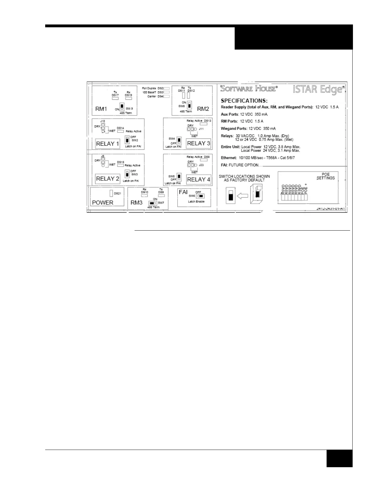
Specifications
17
Door Map
The Door Map shows the location of the Switches, Jumpers, and LEDs.
FIGURE 5. Door Map
Visual Indicators
LCD
LCD will display diagnostic messages in a similar way to the iSTAR eX.
Diagnostics are controlled by the rotary switch, SW1.
Contrast controlled by potentiometer, RV1.
Backlight is ON when door is open, OFF when door is closed, and during
power-fail backups.
LEDs
The super-bright white Power LED is illuminated when the enclosure door is
closed, i.e. when the tamper switch closes. The power LED normally runs at
12VDC and extinguishes at about 8VDC.
The relay activation LEDs remain active regardless of the state of the enclosure
door.
The balance of the indicators are illuminated when the enclosure door is
opened. The LCD backlight and all LEDs other than the power LED and the
relay LEDs are under firmware control and are extinguished when the unit
detects input power failure and enters sleep mode to minimize power
consumption.