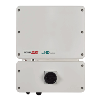
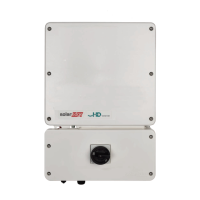
AC conduit entry - for AC connection to the grid or Backup Interface
DCconduit entry - for DCconnection to SolarEdge Power Optimisers and one or
more batteries. When installing a battery, connect the DC cables from the battery
and from Power Optimisers to an external combiner box, compliant with local
regulation. Then, connect the cables from the combiner box to the DCterminals
inside the inverter's Connection Unit.We recommend using the SolarEdge combiner
box. For installation and connection instructions see:
https://www.solaredge.com/sites/default/files/se-combiner-box-installation-guide-
aus.pdf
CT gland -for connection of external CTs
DCSafety switch - connects and disconnects the DC power to the system
Two communication glands: for connection of inverter communication options.
Each gland has three openings.
ON/OFF/P switch:
ON (1) - Turning this switch ON (after Power Optimiser pairing) starts the
operation of the power optimizers, enables power production and allows the
inverter to begin exporting power to the utility grid.
OFF (0) - Turning this switch OFF reduces the power optimizer voltage to a low
safety voltage and inhibits exportation of power. When this switch is OFF, the
control circuitry remains powered up.
Single Phase Energy Hub Inverter MAN-01-00812-1.1
22 Inverter Interfaces
 Loading...