NOTE
Additional SolarEdge inverters (without batteries) can be connected with
RS485. The inverters will participate in export limitation and Smart Energy
Management.
Connecting multiple inverters with RS485 master-slave connection may
require an
RS485 Expansion Kit
(available from SolarEdge).
PV modules connected to power optimizers are not mandatory for charge/
discharge profile programming and for backup power.
Additional Reference
This document describes basic system connection and configuration -
PVsystem (power optimizer strings), one inverter, one battery, backed-
up loads panel and one meter.
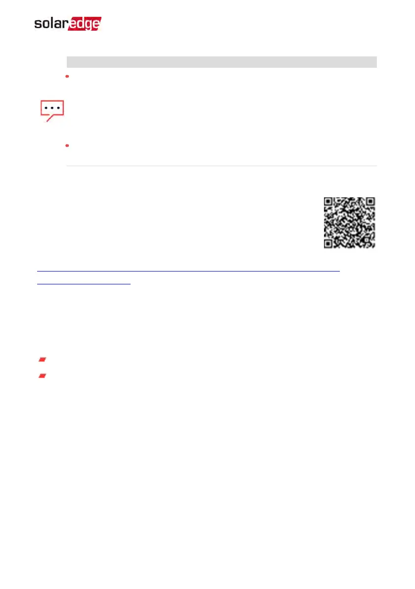
For additional configuration options refer to the StorEdge Solution
Applications - Connection and Configuration Guide, available at
https://www.solaredge.com/sites/default/files/storedge_applications_connection_and_
configuration_guide_na.pdf.
Installation Workflow
When installing the StorEdge system, follow this workflow to ensure all the components
are connected and functioning correctly.
Step 1 - PVsystem installation - modules, power optimizers and inverter:
Power optimizers - as described in
Installing the Power Optimizers
on page 20.
Inverter - as described in
Installing the Inverter
on page 31.
Step 2 - SolarEdge Auto-transformer and ACload panel installation (required for
Backup Power only): Refer to
Auto-transformer and Backed-up Loads Panel Installation
(for Backup)
on page 40.
Step 3 - Energy Meter installation (required for Smart Energy Management only). Refer
to
Meter Installation
on page 43.
Step 4 - Connecting PVstrings (DC) to the inverter - Refer to
Connecting the Strings to
the Inverter
on page 58.
Step 5 - Connecting the battery to the inverter and mounting the battery. Refer to the
installation information in the manufacturer documentation, and to
StorEdge Inverter
Connections
on page 56.
Chapter 1: Overview 17
StorEdge Solution with Backup MAN-01-00262-1.5