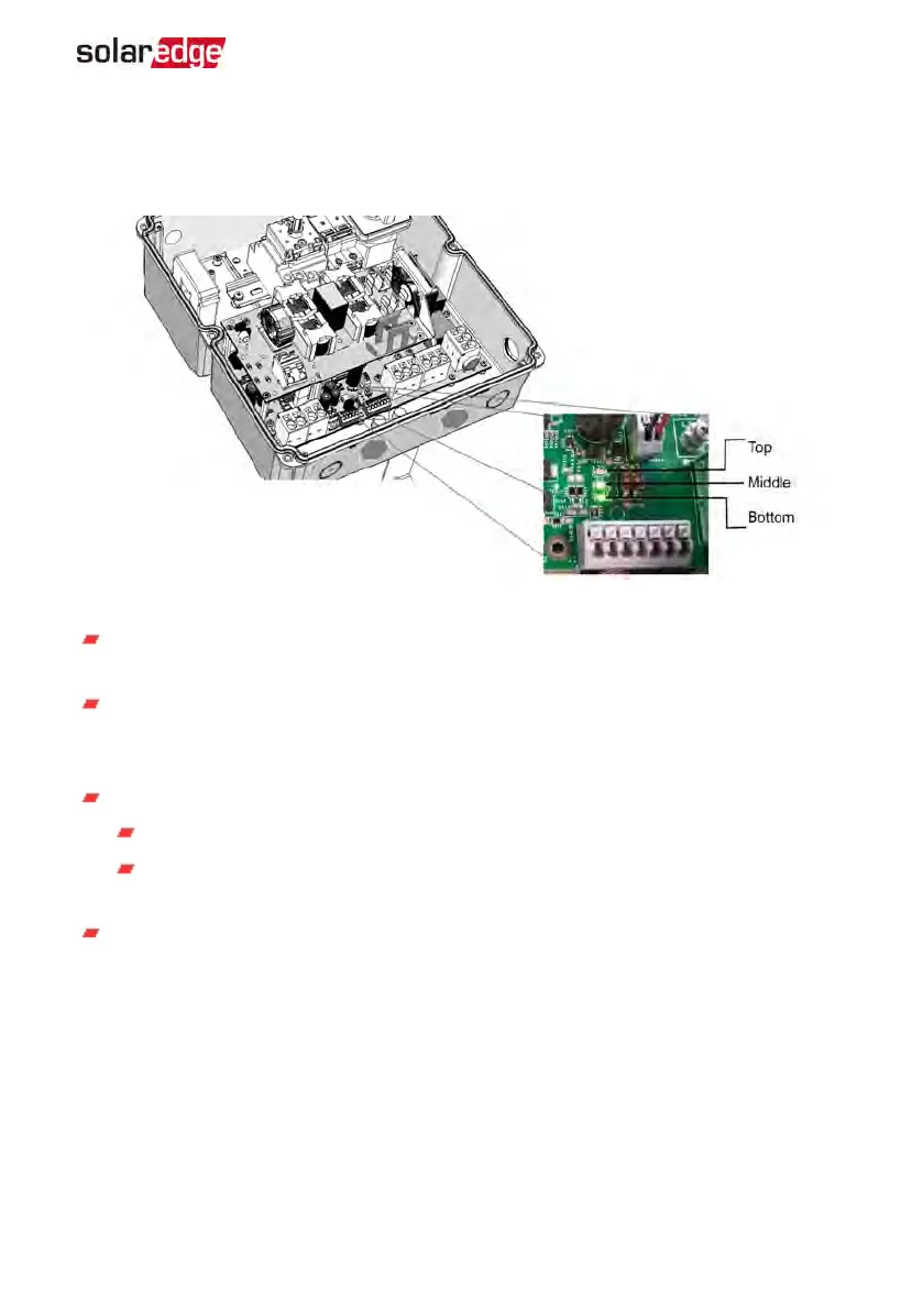
StorEdge Connection Unit LEDs
There are three LEDs on the lower board of the StorEdge Connection Unit, near the DIP
switches:
Figure 44: StorEdge Connection Unit LEDs
In normal operation, the middle and bottom LEDs indicate auxiliary voltages (13V
from DC/DC, 5V and 3.3V) and should always be lit.
The top LEDshould be lit when the inverter DC voltage is at least 200 Vdc (check
when both inverter ON/OFFswitch and StorEdge Connection Unit switch are ON).
You can check the status screen for the Vdc value.
If all LEDs are OFF:
Check that AC voltage exists in the inverter
Check that the communication cable between the StorEdge Connection Unit
and the digital board is properly connected.
If the top LED is ON, and middle and bottom LEDs are off - an internal failure has
occurred. Contact SolarEdge support.
Appendix A: Troubleshooting 127
StorEdge Solution with Backup MAN-01-00262-1.5