19
en
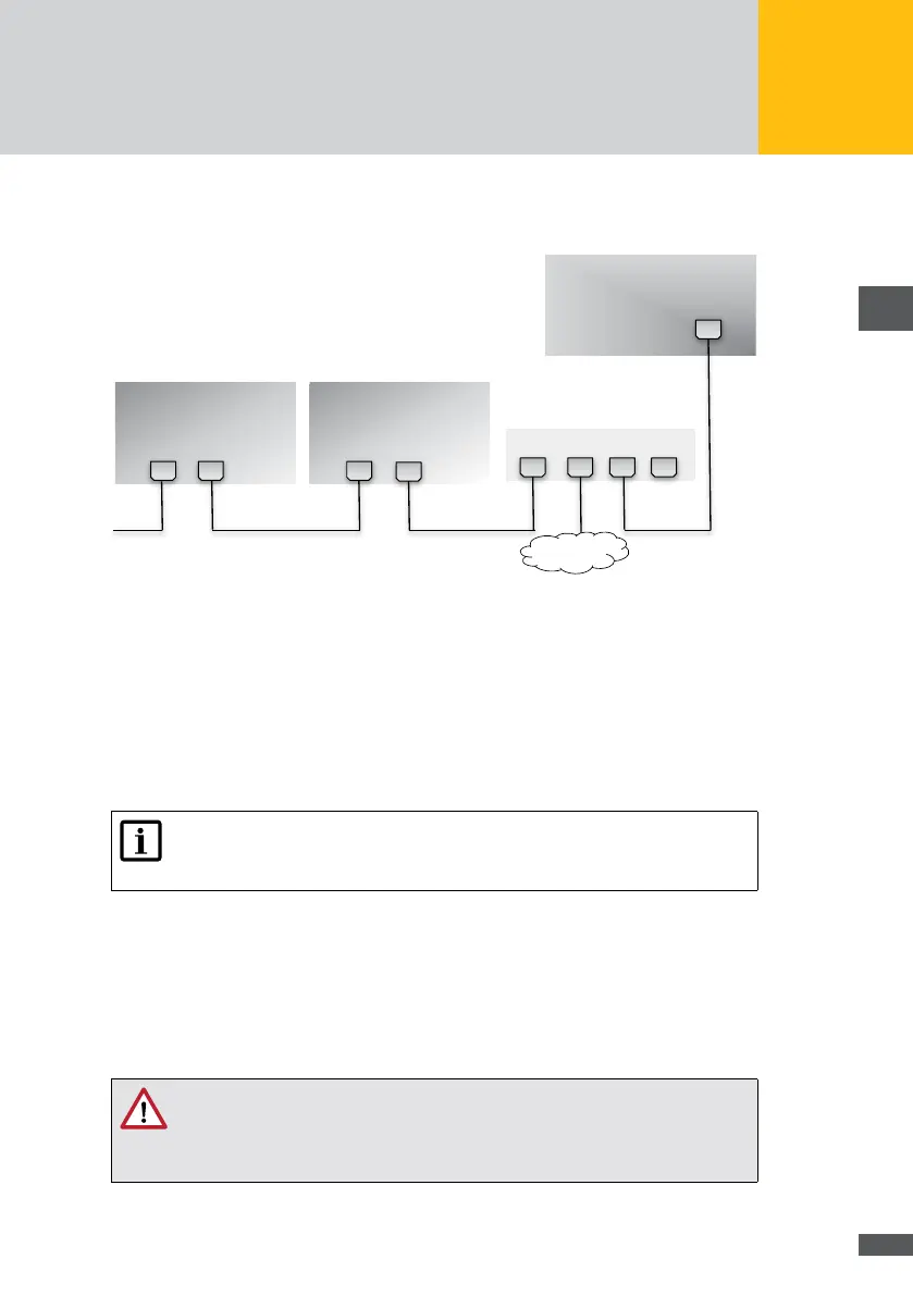
The gure below shows a wiring example for connecting the inverters via the Ethernet
interface.
MaxWeb XPN
Fig. 7: Connecting the inverters via the Ethernet interface
5�4 Addressing
For the MaxWeb XPN to be able to detect connected devices, you must assign an unam-
biguous device address to every device. Please note that each device address must be
used once only. You will nd instructions for setting the address in the product description
of the corresponding device.
Note
The device address is the address of the connected devices within the Max-
Comm network. The device address and the IP address are not identical.
5�5 Power supply
The data logger is supplied with power by the plug-in power supply unit included in the
scope of delivery.
WARNING!
Risk of fire when using unsuitable power supply units!
For power supply, you must use the plug-in power supply unit included in the
scope of delivery.