68
Description of terminals on the front
Terminal Function Limit values
Analogue
measurement
inputs
A1…A4 e.g. irradiance, temperature 4 … 20 mA
GND GND for signal and V+
V + Supply voltage for the sensors at
A0 … A3
15 … 24Vdc / max. 0,5 A
S0 pulse
S0_A –
S0_B –
Connection of the electricity meter
S0_A +
S0_B +
Connection of the electricity meter
CAN bus
V
Iso
Galvanically isolated supply voltage 15 Vdc / max. 0,5 A
GND
Iso
GNDIso for Viso, galvanically isolated
from GND
CAN LOW CAN signal (low dominant) 0 … 8V
CAN HIGH CAN signal (high dominant) 12 … 26V
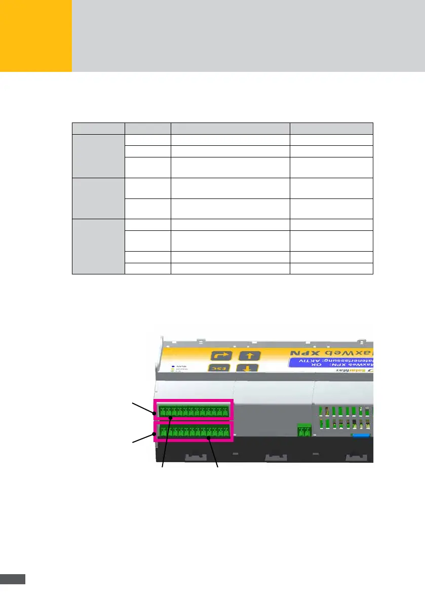
8�5�2 Terminal assignment on the back of the MaxWeb XPN
Back, terminals
at the top
Back, terminals
at the bottom
1 12
1 12
Relay outputs
Block 5
Digital inputs
Block 6
Fig. 68: Terminal assignment on the back of the MaxWeb XPN