7. Operation7. Operation
7.5.12.2 Backflow Power
->Set Backflow Power
Figure 7. Set the power 23backflow
Figure 7.24
Press the UP/DOWN keys to set data.Press the ENTER key to set backflow power.
Then press DOWN keys to move the cursor, press UP to change the number.
Press the ESC key to save the settings and return to the previous menu.
The setting is used to define the allowed export power into the grid.
The setting range is between 00000W to 29900W.
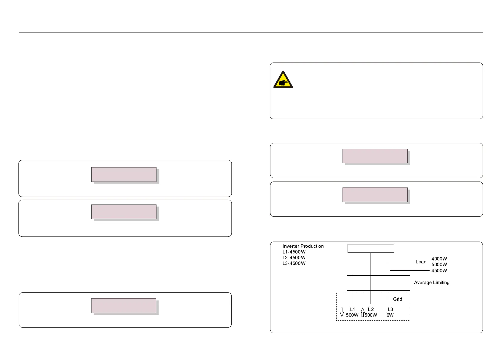
Mode “01”, As shown in the figure 7.28, the average limiting mode, the output power of each
phase is the average of the three-phase load power, and it is more than the phase of the
lowest power in three phases.
Inverter
Meter
Figure 7.28
YES=<ENT> NO=<ESC>
Power:-00000W
7.5.12.4 Backflow Work Mode
This submenu is used for set backflow work mode: 01, 02. “01” is the default mode.
Figure 7.26 Set the Backflow work mode
->Backflow Work Mode
Figure 7.27
YES=<ENT> NO=<ESC>
Mode:01
.39..38.
Select EPM Settings from the Main Menu to access the following options:
1. Mode Select 2.Backflow Power 3.Fail safe ON/OFF 4.Backflow Work Mode
7.5.12.1 Mode Select
There are 4 settings in this menu as below:
1. OFF 2. Meter in Load 3. Meter in Grid 4.Consumption Monitor
OFF: Functions are disabled
Meter in Load: Solis Smart Meter is connected in the load branch circuit.
Meter in Grid: Solis Smart Meter is connected in the grid connection point
(The backflow power is default as 0W).
Consumption Monitor: Solis Smart Meter is connected in the grid connection point
(The backflow power setting is not applicable).
7.5.12.3 Fail safe ON/OFF
This setting is used to give out an alarm (stop inverter generation as well) when the Meter
connection is lost during operation.
It can prevent potential backflow power into the grid when the system loses control.
Figure 7.25 Set the Fail Safe ON/OFF
YES=<ENT> NO=<ESC>
Fail Safe Set:ON
It is only mandatory to turn on this function when the inverter is installed in UK due to the G100
regulation. For other regions,customers can enable or disable the function as they desire.
NOTE:
When the failsafe function is ON and CT/Meter is disconnected somehow,
the inverter will stop generation and give "Failsafe" alarm on the LCD.
When the failsafe function is OFF and CT/Meter is disconnected somehow,
the inverter will keep the output power as the last moment when the
CT/Meter is still connected. After a restart, the inverter will output at full
power without limit.
 Loading...