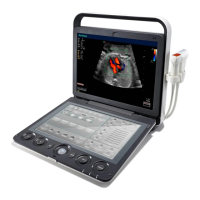
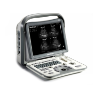
6 Acquiring Images
70 Basic User Manual
■ Steer
Steer can be adjusted to change the direction of the acoustic beam when performing a real time scan by using the
linear probes.
To adjust the steer:
Tap the left or right part of
Steer
on the touch screen to change the direction of the acoustic beam.
NOTE:
Only the linear probes are capable of using the steer.
6.3 Acquiring Color Flow Images
Color Flow imaging adds the color-coded qualitative information in the B-Mode image. Color Flow imaging is
helpful to see the ow, the relevant qualitative information and the ow velocity.
6.3.1 CFM Mode
CFM is a color ow imaging technology which adds the color-coded qualitative information concerning the relative
velocity and direction of uid motion in the B-Mode image.
Perform the following steps to acquire CFM-mode images.
1. Optimize a B-mode image.
2. Press the
CFM
key on the control panel to enter the CFM mode.
0
5
10
15
9
-9
cm/s
2D Imaging
Color Flow ROI
B
FPS 47
D/G 3/1
GN 255
I/P 3/30
PWR 70
FRQ 3-4.8
D 16.5cm
C
PRF 1.0
WF 86
GN 255
C/P 1/50
PWR 70
FRQ 2.2
S
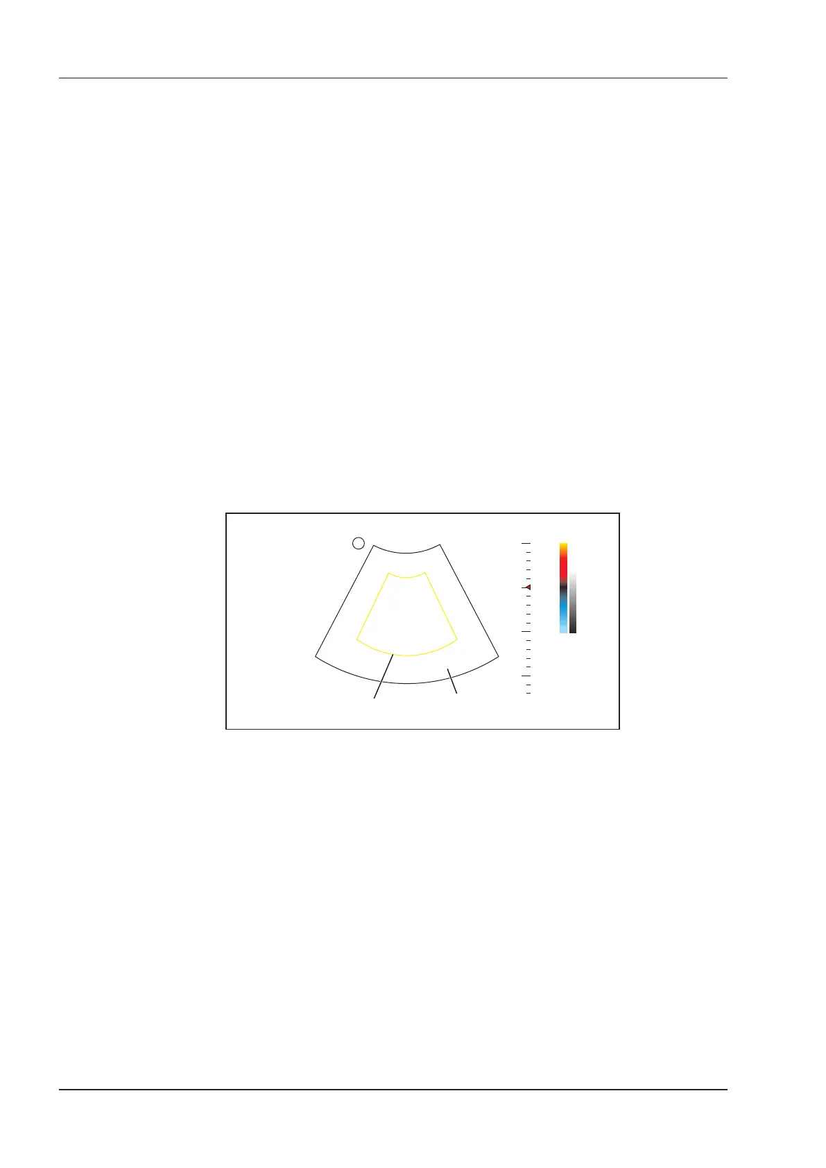
Figure 6-6 CFM-Mode Imaging Screen
3. Adjust color ow ROI.
−
Move the trackball to position color ow ROI.
−
Press the conrm key on the control panel to adjust the size of color ow ROI.
−
Press the conrm key again to reposition color ow ROI.
4. Optimize the CFM-mode image. For details, refer to Section 6.4.3 Optimizing M-Mode Images.
5. Press the
CFM
key again to exit the screen.
6.3.2 PDI Mode
PDI (Power Doppler Imaging) is a color ow imaging technology which adds the ow signal in the CFM-mode
image. PDI uses the number and amplitude of red blood cells going through in the flow to create the color-
coded imaging. A ow with slow velocity and small rate can be displayed in PDI. Therefore, a ow with a higher
sensitivity can be detected without overlaying any ows with high velocity.
The direction of ow, the ow velocity and ow properties cannot be reected in the PDI-Mode image.
Perform the following steps to acquire PDI-mode images: