EasyManua.ls Logo

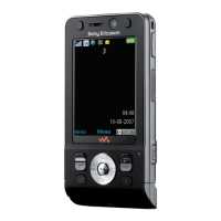
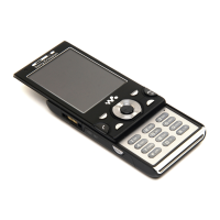
Sony Ericsson W910 User Manual

Sony Ericsson W910
34 pages
To Next Page IconTo Next Page
Page #1 background imageLoading...
Page #1 background image
Working Instruction, Mechanical
3/000 21-1/FEA 209 544/129 A
Company Internal
©
Sony Ericsson Mobile Communications AB
1(34)
Working Instruction, Mechanical
Applicable for W910
CONTENTS
1
Introduction .............................................................................. 3
1.1
Equipment.................................................................................4
1.2
General cautions ......................................................................5
1.3
Adhesives .................................................................................5
2
Disassembly ............................................................................. 6
2.1
Overview ...................................................................................6
2.1.1 M2, Battery Cover and Battery ..............................................7
2.1.2 Rear Back Cover ...................................................................8
2.1.3 Main PCB ............................................................................10
2.1.4 Front Cover Assembly......................................................... 11
2.1.5 Navi Key PBA...................................................................... 13
2.1.6 Display ................................................................................13
3
Replacements......................................................................... 14
3.1
Battery Cover..........................................................................15
3.2
Battery .....................................................................................15
3.3
RF Cap.....................................................................................15
3.4
Label Co-Brand Inlay .............................................................15
3.5
Keyboard Main........................................................................15
3.6
Liquid Intrusion Indicator......................................................16
3.7
Panel Antenna ........................................................................16
3.8
Rear Back Cover.....................................................................16
3.9
Key, On/Off..............................................................................16
3.10
Key, Volume............................................................................16
3.11
Key, Camera............................................................................16
3.12
Key, Music...............................................................................17
3.13
Cap, MemoryStick ..................................................................17
3.14
Camera 2.0 MPixel CMOS ......................................................17
3.15
BT Antenna Assy....................................................................17
3.16
Front Cover Assembly ...........................................................18
3.17
Key, Game...............................................................................18
3.18
Key, Navi .................................................................................18
3.19
Navi Key PBA..........................................................................18
3.20
Display.....................................................................................18
3.21
Slider Flex Module..................................................................18
3.22
Slider Sub Assembly..............................................................18
3.23
Main Antenna..........................................................................19

Other manuals for Sony Ericsson W910

Question and Answer IconNeed help?

Do you have a question about the Sony Ericsson W910 and is the answer not in the manual?

Sony Ericsson W910 Specifications

General IconGeneral
Network TechnologyGSM / HSPA
2G bandsGSM 850 / 900 / 1800 / 1900
GPRSClass 10
EDGEClass 10
StatusDiscontinued
Dimensions99.5 x 50 x 12.5 mm (3.92 x 1.97 x 0.49 in)
SIMMini-SIM
TypeTFT, 256K colors
Memory Card slotMemory Stick Micro (M2), up to 4 GB
Phonebook1000 entries, Photo call
Call records30 received, dialed and missed calls
Internal40 MB
Primary Camera2 MP
Secondary CameraNo
Alert typesVibration; Downloadable polyphonic, MP3 ringtones
LoudspeakerYes
3.5mm jackNo
WLANNo
Bluetooth2.0, A2DP
GPSNo
USB2.0
BrowserWAP 2.0/xHTML, HTML (NetFront)
GamesYes + downloadable
JavaYes, MIDP 2.0
Operating SystemProprietary
3G bandsUMTS 2100
SpeedHSPA 3.6/384 kbps
Announced2007, June
Size2.4 inches
Resolution240 x 320 pixels
RadioStereo FM radio
MessagingSMS, MMS, Email
BatteryRemovable Li-Po 930 mAh battery
Stand-byUp to 350 h (3G)
Talk timeUp to 9 h (2G)
ColorsBlack, Red
Weight86 g (3.0 oz)

Summary

Introduction

General Cautions

Provides essential safety precautions applicable to all disassembly and reassembly procedures.

Disassembly

M2, Battery Cover, and Battery Removal

Step-by-step guide to removing the MemoryStick, battery cover, and battery.

Rear Back Cover Removal

Detailed instructions for removing the rear back cover, including screw removal.

Main PCB Removal

Procedure for removing the main printed circuit board (PCB), including antenna coax.

Front Cover Assembly Disassembly

Steps for disassembling the front cover assembly, including screw removal and careful prying.

Navi Key PBA Removal

Instructions for removing the Navi Key Printed Circuit Board Assembly (PBA).

Display Removal

Procedure for carefully sliding and removing the phone's display unit.

Replacements

2.0 MPixel CMOS Camera Replacement

Detailed steps for replacing the 2.0 MPixel CMOS camera module.

Front Cover Assembly Replacement

Steps for replacing the front cover assembly, referencing disassembly and reassembly.

Navi Key PBA Replacement

Instructions for replacing the Navi Key Printed Circuit Board Assembly (PBA).

Display Replacement

Procedure for replacing the phone's display unit, referencing disassembly and reassembly.

Reassembly

Front Cover Assembly Reassembly

Steps for positioning the front cover assembly, pressing it into place, and securing screws.

Main PCB Reassembly

Procedure for connecting flex cables to the main PCB and folding it into position.

Related product manuals