5-28
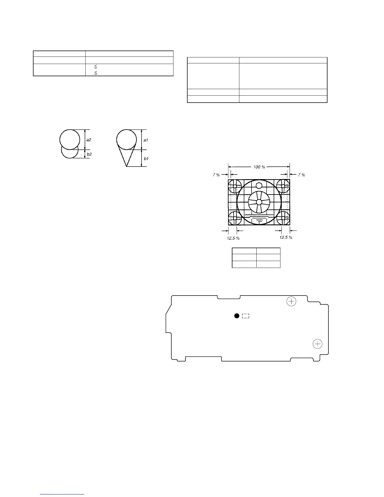
1-5-4. Aberration Adjustment
Mode VTR stop
Signal Dot pattern
Specified Value b1 2 • a1
b2 0.8 • a2
Adjusting method:
1) Adjust the aberration adjustment ring so that the tracing of the
dot satisfies the specified value.
2) If the centering becomes displaced here, perform the centering
adjustment from the beginning again.
Fig. 5-1-19.
1-5-5. Horizontal Amplitude Adjustment
(VF-99 board)
Mode Playback
Signal Alighment tape :
For checking operations
(WR5-5CSP)
Monoscope section
Adjusting Element C909 (SOL901)
Specified Value ± 1.5 °
Adjusting method:
1) Rotate RV903, and adjust the top and bottom sides of the
monoscope image to the top and bottom edges of the display.
2) Rotate RV904 so that the brightness is the normal level.
3) Solder or unsolder SOL901 pattern of the H size adjustment ca-
pacitor (C909) to “short” or “open”, so that the horizontal
direction over scan becomes 14 ± 6% (Left and right totals).
Fig. 5-1-20.
SOL901 Size H
Open Small
Short Big
C909
SOL901
RV903
RV904
VF-99 BOARD (SIDE A)