5-30
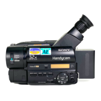
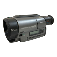
1-6. LCD SYSTEM ADJUSTMENT (TRV SERIES)
Note1: The back light (fluorescent tube) is driven by a high volt-
age AC power supply. Therefore, do not touch the back
light holder to avoid electrical shock.
Note2: When replacing the LCD unit, be careful to prevent dam-
ages caused by static electricity.
Note3: Set the brightness to the center using the LCD BRIGHT
button.
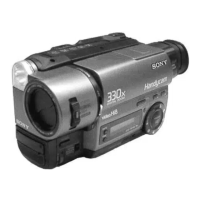
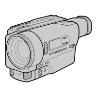
Note4: LCD model :
CCD-TRV16E/TRV26E/TRV27E/TRV27EP/
TRV36E/TRV46E
[Adjusting connector]
Most of the measuring points for adjusting the LCD display are
concentrated in the following connector.
CN5501 of the PD-107 board
Connect the measuring instruments via the multi CPC jig (J-6082-
311-A).
The following table shows the Pin No. and signal name of the con-
nector.
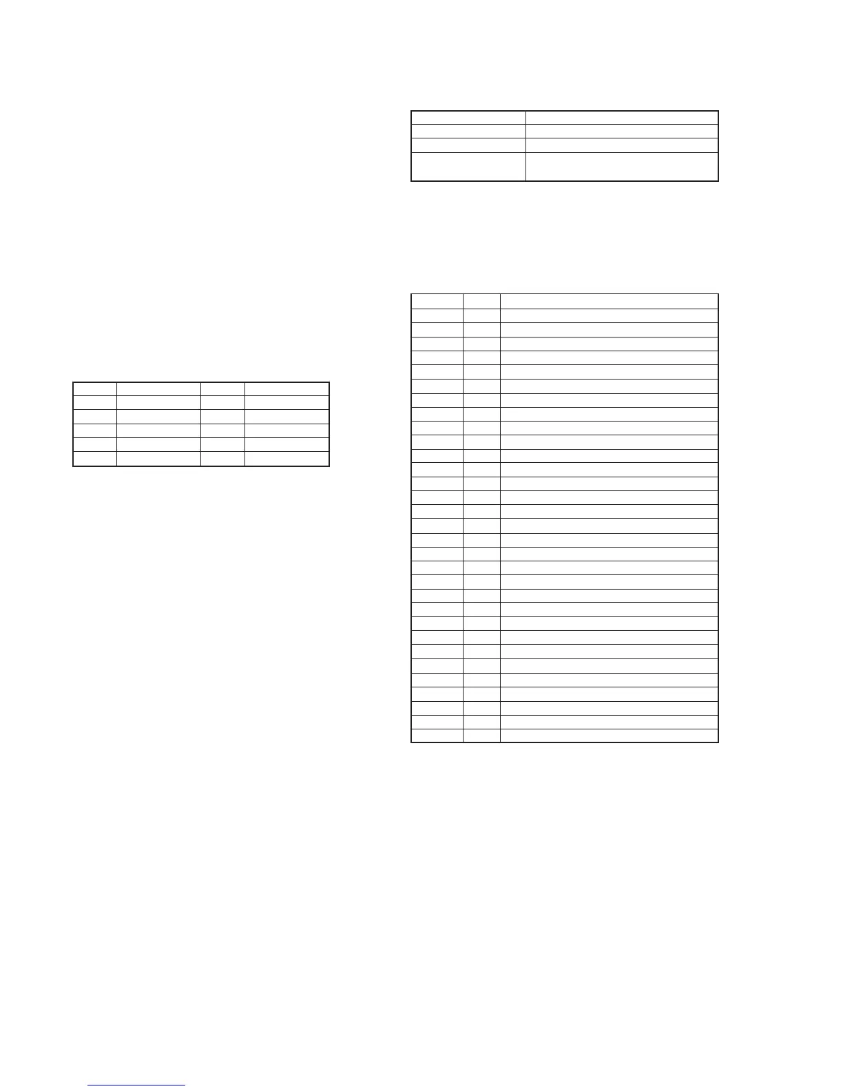
Pin No. Signal name Pin No. Signal name
1 VB 2 VCO VOLTAGE.
3 VG 4 PANEL COM
5 VR 6 N.C.
7 SYNC / HD 8 H START
9 GND 10 GND
1. LCD Initial Data Input
Mode VTR stop
Signal Arbitrary
Adjustment Page E
Adjustment Address A5 to A7, B0 to B9, BF, C0, C1, CF,
D0 to DD
Adjusting method:
1) Select page: 0, address: 01, and set data: 01.
2) Select page: E, and input the data in the following table.
Note: To write in the non-volatile memory (EEPROM), press
the PAUSE button of the adjusting remote commander each
time to set the data.
3) Select page: 0, address: 01, and set data: 00.
A5 53 Fixed value
A6 96 Fixed value
A7 68 Fixed value
B0 3F Fixed value
B1 C8 Fixed value
B2 1F Fixed value
B3 1F Fixed value
B4 00 Fixed value
B5 00 Fixed value
B6 F0 Fixed value
B7 4E Fixed value
B8 08 Fixed value
B9 00 Fixed value
BF 80 Fixed value
C0 A4 Fixed value
C1 CF Fixed value
CF 84 Bright adjustment
D0 77 Color adjustment
D1 98 White balance adjustment
D2 7B White balance adjustment
D3 DC Contrast adjustment
D4 80 D range adjustment
D5 89 V-COM level adjustment
D6 80 VCO adjustment
D7 80 V-COM level adjustment
D8 80 Fixed value
D9 77 Fixed value
DA 80 Fixed value
DB 52 Fixed value
DC 99 Fixed value
DD 99 Fixed value
Address Data Remark