5-31
2. VCO Adjustment (PD-107 board)
Set the VCO freerun frequency. If deviated, the LCD screen will be
blurred.
Mode VTR stop
Signal No signal
Measurement point Pin 2 of CN5501 (VCO VOLTAGE)
of PD-107 board
Measuring instrument Oscilloscope
Adjustment page E
Adjustment address D6
Specified value A = 1.70 ± 0.02V
Adjusting method:
1) Select page: 0, address: 01, and set data: 01.
2) Select page: 3, address: 01, set data: 55, and press the PAUSE
button of the adjusting remote commander.
3) Select page: 2, address: 7D, and set data: 00.
4) Select page: E, address: D6, change the data and set the VCO
VOLTAGE (A) to the specified value.
5) Press the PAUSE button of the adjusting remote commander.
6) Select page: E, address: D6, and read the data (DD6).
7) Calculate the adjustment data (hexadecimal) from the follow-
ing equations (hexadecimal calculation), and input to address:
BF. (Refer to Table 5-1-2. Hexadecimal-Decimal conversion
Table.)
When DD6 55
DBF = DD6 - 55
When DD6 < 55
DBF = 00
Note2 : After setting data, be sure to press the PAUSE button.
8) Select page: 3, address: 01, set data: 00, and press the PAUSE
button of the adjusting remote commander.
9) Select page: 0, address: 01, and set data: 00.
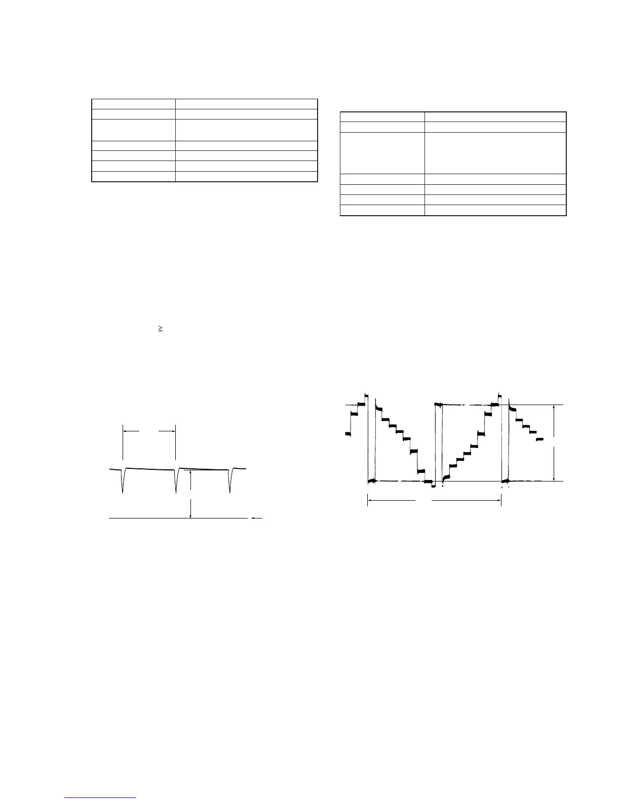
Fig. 5-1-22.
3. D range Adjustment (PD-107 board)
Set the D range of the RGB decoder used to drive the LCD to the
specified value. If deviated, the LCD screen will become blackish
or saturated (whitish).
Note1 : Press the DISPLAY button and erase the screen indictors
on the LCD screen.
Adjusting method:
1) Select page: 0, address: 01, and set data: 01.
2) Select page: 3, address: 01, set data: 55, and press the PAUSE
button of the adjusting remote commander.
3) Select page: 2, address: 7D, and set data: 00.
4) Select page: E, address: D4, change the data and set the voltage
(A) between the reversed waveform pedestal and non-reversed
waveform pedestal to the specified value.
5) Press the PAUSE button of the adjusting remote commander.
6) Select page: 3, address: 01, set data: 00, and press the PAUSE
button of the adjusting remote commander.
7) Select page: 0, address: 01, and set data: 00.
Mode VTR stop
Signal No signal
Measurement point Pin 3 of CN5501 (VG) of PD-107
board
External trigger : Pin 4 of CN5501
(PANEL COM)
Measuring instrument Oscilloscope
Adjustment page E
Adjustment address D4
Specified value A = 2.98 ± 0.05V
Fig. 5-1-23.
H
A
GND level
(0 Vdc)
A
2H