5-49
3. Filter f0 Adjustment (VC-215 board)
Minimize the chroma signal residual components during compos-
ite video signal input.
Mode VTR stop
Signal No signal
Measurement Point Pin 3 of CN910 (IR VIDEO)
Measuring Instrument Oscilloscope
Adjustment Page F
Adjustment Address 4D
Specified Value Minimum residual chroma signal
components (A = Bellow 35mV)
Switch setting:
LASER LINK .................... ON (Red LED is lit)
Adjusting method:
1) Select page: 0, address: 01, and set data: 01.
2) Select page: 3, address: 01, set data: 4F, and press the PAUSE
button of the adjusting remote commander.
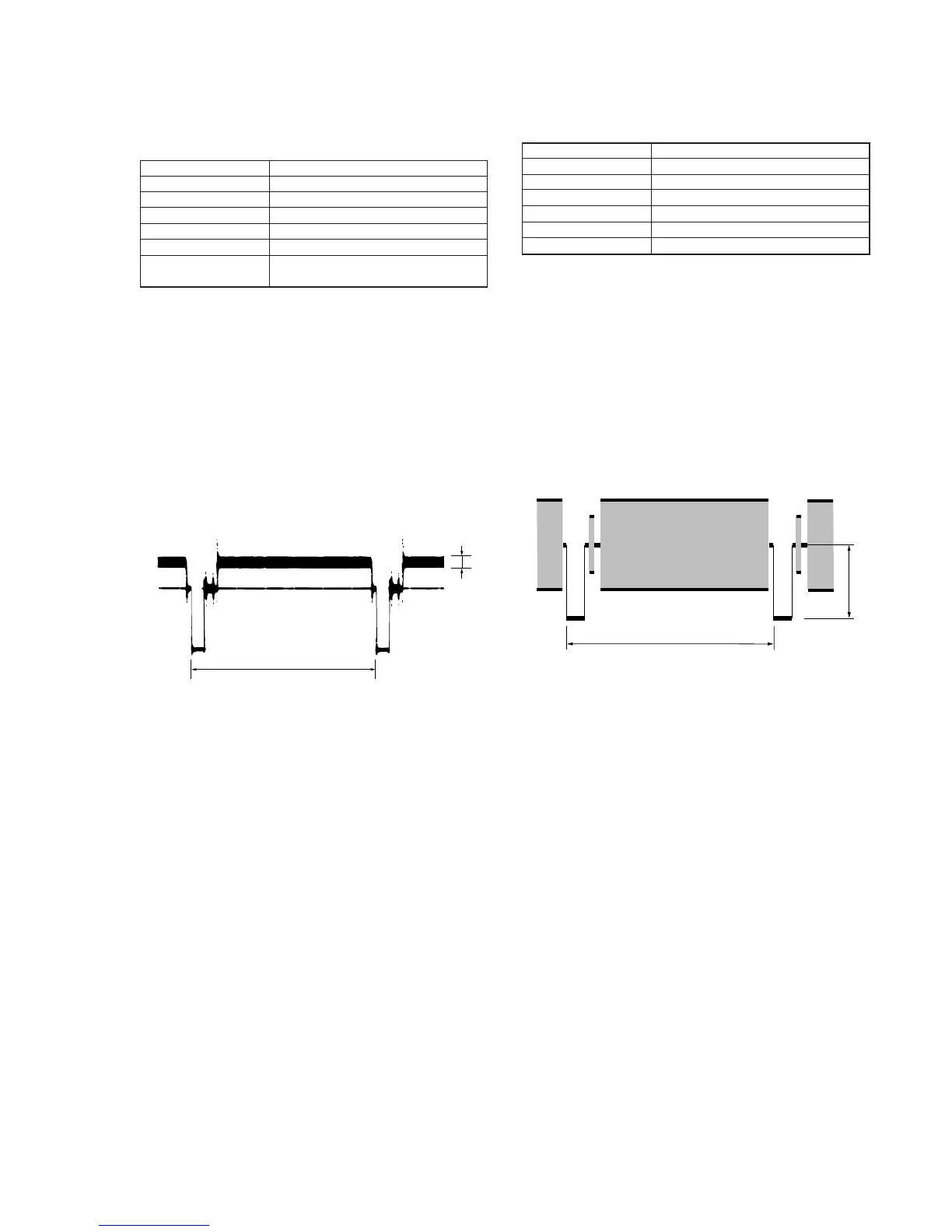
3) Select page: F, address: 4D, change the data and minimize the
residual chroma signal components (A).
4) Press the PAUSE button of the adjusting remote commander.
5) Select page: 3, address: 01, set data: 00, and press the PAUSE
button of the adjusting remote commander.
6) Select page: 0, address: 01, and set data: 00.
Fig. 5-3-7.
A
H
4. Y OUT Level Adjustment (VC-215 board)
Set the Y signal output level.
Mode VTR stop
Signal No signal
Measurement Point VIDEO terminal (75Ω terminated )
Measuring Instrument Oscilloscope
Adjustment Page F
Adjustment Address 49
Specified Value A = 300±5mV
Adjusting method:
1) Select page: 0, address: 01, and set data: 01.
2) Select page: 3, address: 01, set data: 41, and press the PAUSE
button of the adjusting remote commander.
3) Select page: 2, address: 61, and set data: 30, and press the PAUSE
button of the adjusting remote commander.
4) Select page: F, address: 49, change the data and set the SYNC
level (A) to the specified value.
5) Press the PAUSE button of the adjusting remote commander.
6) Select page: 2, address: 61, and set data: 10.
7) Select page: 3, address: 01, set data: 00, and press the PAUSE
button of the adjusting remote commander.
8) Select page: 0, address: 01, and set data: 00.
Fig. 5-3-8.