5-50
6. RP Filter f0 Adjustment (VC-215 board)
Adjust the LPF of the playback RF amplifier.
Mode VTR stop
Signal No signal
Measurement Point Pin 9 of CN910 (RF AGC OUT)
Measuring Instrument Oscilloscope
Adjustment Page F
Adjustment Address 4E
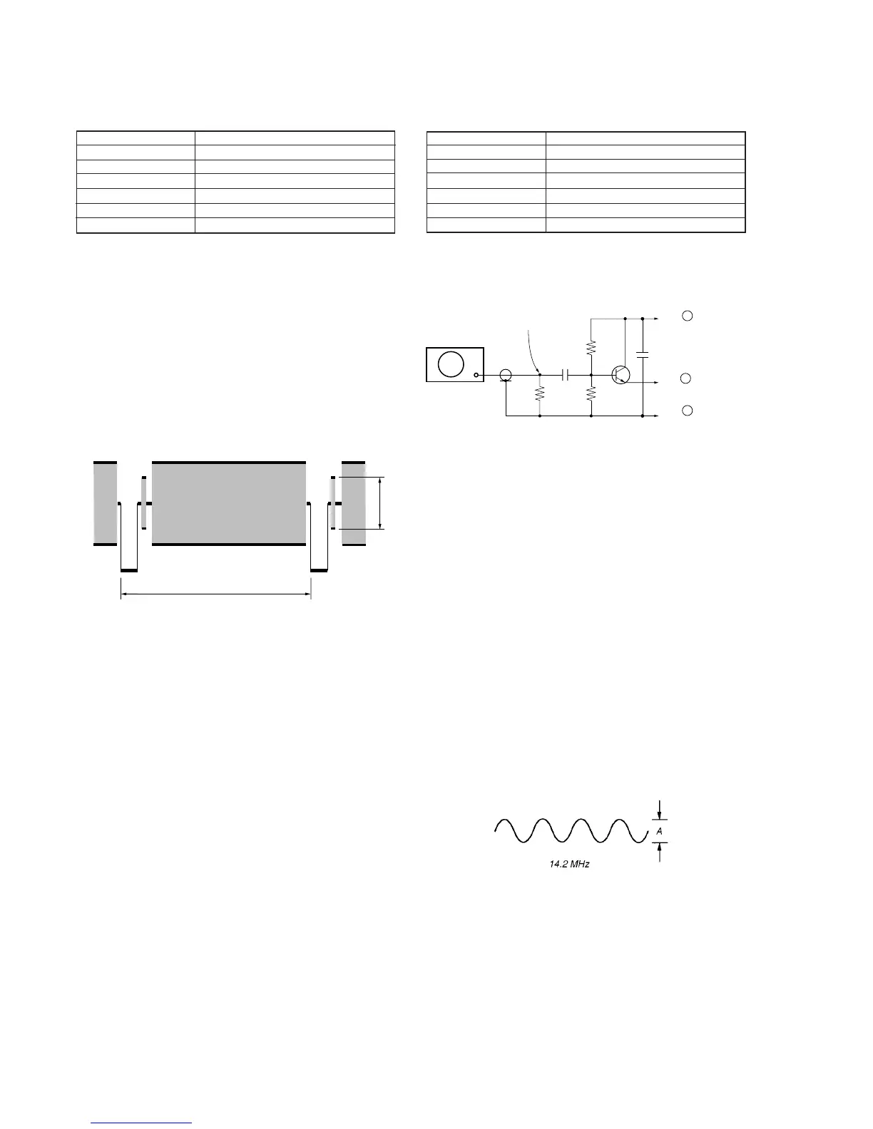
Specified Value A = Below 10mVp-p
Connection:
1) Input a 14.2MHz, 400mVp-p CW signal to Pin 7 of CN910
(RF AGC IN).
Fig. 5-3-10.
Adjusting method:
1) Select page: 0, address: 01, and set data: 01.
2) Select page: 3, address: 01, set data: 35, and press the PAUSE
button of the adjusting remote commander.
3) Only for Standard8 model, select page: D, address: 15, after
memorizing the data , set the bit value of bit0 to “1”. (Refer to
“3. Bit value discrimination” of “3-1-8. Service mode”).
4) Select page: F, address: 4E, change the data and minimize the
14.2 MHz signal level (A).
5) Press the PAUSE button of the adjusting remote commander.
6) Select page: D, address: 15, and set the data memorized at step
3), and press the PAUSE button of the adjusting remote
commander..
7) Select page: 3, address: 01, set data: 00, and press the PAUSE
button of the adjusting remote commander.
8) Select page: 0, address: 01, and set data: 00.
Fig. 5-3-11.
Signal
generator
14.2MHz 400mVp-p
0.01
µ
F
0.01
µ
F
15k
Ω
1k
Ω
47
Ω
Pin 5 of CN101 of
PJ-90/91 board
Pin 7 of CN910
(RF AGC IN)
Pin 8 of CN910
(REG GND)
Transistor : General NPN transistor (2SC403. etc)
47
Ω
resistor :
1k
Ω
resistor :
15k
Ω
resistor :
0.01
µ
F capacitor :
1-249-401-11
1-249-417-11
1-249-431-11
1-101-004-00
5. C OUT Level Adjustment (VC-215 board)
Set the chroma signal output level.
Mode VTR stop
Signal No signal
Measurement Point VIDEO terminal (75Ω terminated )
Measuring Instrument Oscilloscope
Adjustment Page F
Adjustment Address 4B
Specified Value A = 300±5mV
Adjusting method:
1) Select page: 0, address: 01, and set data: 01.
2) Select page: 3, address: 01, set data: 41, and press the PAUSE
button of the adjusting remote commander.
3) Select page: 2, address: 61, and set data: 30, and press the PAUSE
button of the adjusting remote commander.
4) Select page: F, address: 4B, change the data and set the burst
level (A) to the specified value.
5) Press the PAUSE button of the adjusting remote commander.
6) Select page: 2, address: 61, and set data: 10.
7) Select page: 3, address: 01, set data: 00, and press the PAUSE
button of the adjusting remote commander.
8) Select page: 0, address: 01, and set data: 00.
Fig. 5-3-9.
A
H