3
TABLE OF CONTENTS
1. GENERAL
Location of controls................................................................. 4
Getting Started......................................................................... 5
Setting the clock ...................................................................... 5
CD Player CD/MD Unit .......................................................... 6
Radio ....................................................................................... 7
RDS ......................................................................................... 9
DAB ....................................................................................... 10
DSP........................................................................................ 11
Other Functions ..................................................................... 12
TV/Video ............................................................................... 14
Connections ........................................................................... 15
2. DISASSEMBLY
2-1. Front Panel Assy (Normal)................................................ 22
2-2. Front Panel Assy (Inoperative).......................................... 22
2-3. CD Mechanism Block, Flexible Board ............................. 23
2-4. Sub Panel (CD) Sub Assy ................................................. 23
2-5. Motor Block Assy, Cam (R) Assy ..................................... 24
2-6. Main Board ....................................................................... 24
2-7. Heat Sink ........................................................................... 25
2-8. Chassis (T) Sub Assy ........................................................ 25
2-9. Lever Section..................................................................... 26
2-10. Servo Board....................................................................... 26
2-11. Shaft Roller Assy .............................................................. 27
2-12. Floating Block Assy .......................................................... 27
2-13. Optical Pick-up Block ....................................................... 28
3. PHASE ALIGNMENT
3-1. Arm (A-L) Assy, Arm (B-L) Assy ..................................... 29
3-2. Cam (L) ............................................................................. 29
3-3. Motor Block ...................................................................... 30
3-4. Alignment between Arm (A-L) Assy
and Arm (B-L) Assy .......................................................... 30
3-5. Arm (A-R) Assy, Arm (B-R) Assy .................................... 31
3-6. Cam (R) ............................................................................. 31
4. DIAGRAMS
4-1. IC Pin Descriptions ........................................................... 32
4-2. Block Diagram –CD Section–........................................... 42
4-3. Block Diagram –Tuner Section– ....................................... 43
4-4. Block Diagram –Display Section–.................................... 44
4-5. Circuit Boards Location .................................................... 45
4-6. Printed Wiring Boards –CD Mechanism Section–............ 46
4-7. Schematic Diagram –CD Mechanism Section (1/2)– ....... 48
4-8. Schematic Diagram –CD Mechanism Section (2/2)– ....... 49
4-9. Printed Wiring Boards –Main Section– ............................ 50
4-10. Schematic Diagram –Main Section (1/4)– ........................ 52
4-11. Schematic Diagram –Main Section (2/4)– ........................ 53
4-12. Schematic Diagram –Main Section (3/4)– ........................ 54
4-13. Schematic Diagram –Main Section (4/4)– ........................ 55
4-14. Printed Wiring Board –Sub Section– ................................ 56
4-15. Schematic Diagram –Sub Section– ................................... 57
4-16. Printed Wiring Board –Display Section– .......................... 58
4-17. Schematic Diagram –Display Section–............................. 59
5. EXPLODED VIEWS
5-1. Chassis Section ................................................................. 62
5-2. Front Panel Section ........................................................... 63
5-3. CD Mechanism Section (1) ............................................... 64
5-4. CD Mechanism Section (2) ............................................... 65
5-5. CD Mechanism Section (3) ............................................... 66
6. ELECTRICAL PARTS LIST ........................................ 67
Ver 1.1 2000. 08
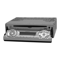
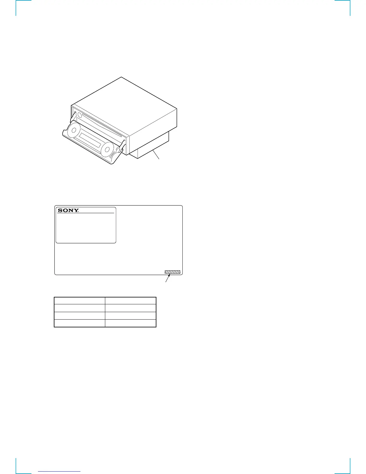
NOTE FOR THE OPENING OF THE FRONT PANEL
In this set, the front panel is lowered to below the bottom face when
it is opened.
When servicing the set, place it on a stand having a height of about
2 cm.
stand
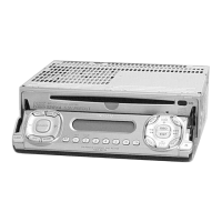
MODEL IDENTIFICATION
CDX-M700R have 3 type models.
Part No. Model
3-046-061-0s TYPE1
3-046-062-0s TYPE2
3-047-828-0s TYPE3
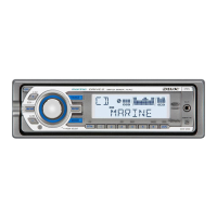
– MODEL NUMBER LABEL –
FM/MW/LW COMPACT DISC PLAYER
Part No.
MODEL No. CDX-M700R
 Loading...