30
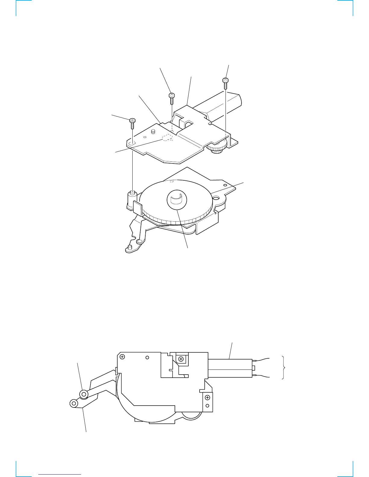
3-3. MOTOR BLOCK
3-4. ALIGNMENT BETWEEN ARM (A-L) ASSY
AND ARM (B-L) ASSY
1 Turn the cam (L) and position the cam so that part A
does not touch the SWITCH board SW900.
1 Input 9V DC to the motor terminal until the cam (L)
stops rotating.
Take care to avoid overload of the motor.
2 Verify that the arm (A-L) assy and arm (B-L) assy
are positioned as shown below (full open).
3 PTT 2.6x6
4 PTT 2.6x6
2 motor block
SWITCH board
SW900
cam (L