58
CX-JT7
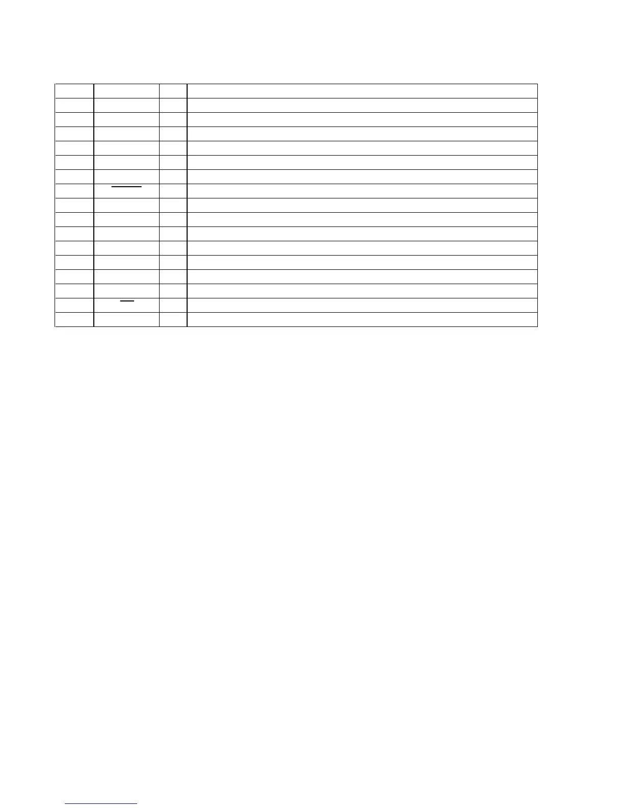
• MAIN BOARD IC310 BU2099FV ( BASS BOOST CONTROLLER)
Pin No. Pin Name I/O Description
1 VSS — Ground terminal
2NC—Not used
3 DATA I Serial data input from the multi controller
4 CLOCK I Serial data transfer clock signal input from the system controller
5 LCK I Serial data latch pulse clock signal input from the system controller
6 to 8 NC — Not used
9 I-BASS O Bass boost on/off control signal output terminal “L”: bass boost on
10 to 12
CTRL3 to CTRL1
O Frequency control signal output terminal
13 BB CTRL4 O Bass boost control signal output terminal “H”: bass boost +10dB
14 BB CTRL3 O Bass boost control signal output terminal “H”: bass boost +8dB
15 BB CTRL2 O Bass boost control signal output terminal “H”: bass boost +6dB
16 BB CTRL1 O Bass boost control signal output terminal “H”: bass boost +5dB
17 NC — Not used
18 SO O Serial data output terminal Not used
19 OE — Not used
20 VDD — Power supply terminal (+3.3V)