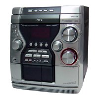
59
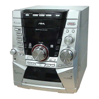
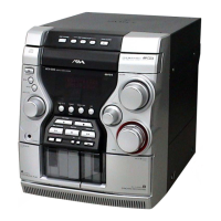
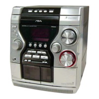
CX-JT7
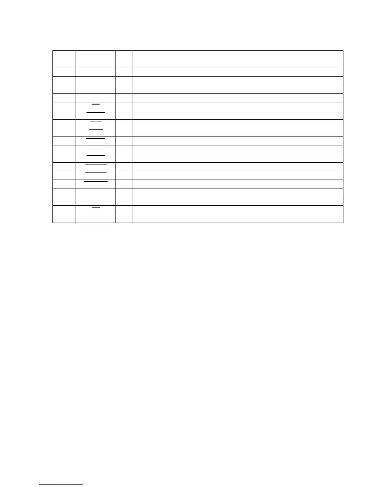
• PANEL BOARD IC201 BU2099FV (LED DRIVER)
Pin No. Pin Name I/O Description
1 VSS — Ground terminal
2NC—Not used
3 DATA I Serial data input from the system controller
4 CLOCK I Serial data transfer clock signal input from the system controller
5 LCK I Serial data latch pulse clock signal input from the system controller
6CDOLED drive signal output of the CD indicator “L”: LED on
7TUNER O LED drive signal output of the TUNER BAND indicator “L”: LED on
8 AUX O LED drive signal output of the MD (VIDEO) indicator “L”: LED on
9 TAPE O LED drive signal output of the TAPE A/B indicator “L”: LED on
10 HEAVY O LED drive signal output of the HEAVY indicator “L”: LED on
11 VOCAL O LED drive signal output of the VOCAL indicator “L”: LED on
12 SALSA O LED drive signal output of the SALSA indicator “L”: LED on
13 TECHNO O LED drive signal output of the TECHNO indicator “L”: LED on
14 HIP HOP O LED drive signal output of the HIP HOP indicator “L”: LED on
15 MANUAL O LED drive signal output of the MANUAL indicator “L”: LED on
16, 17 NC — Not used
18 SO O Serial data output to the tape mechanism controller
19 OE — Not used
20 VDD — Power supply terminal (+3.3V)