34
9. Press the ENTER/YES “R” button display “EFB = MO-P”.
Then, the optical pick-up moves to the pit area automatically
and servo is imposed.
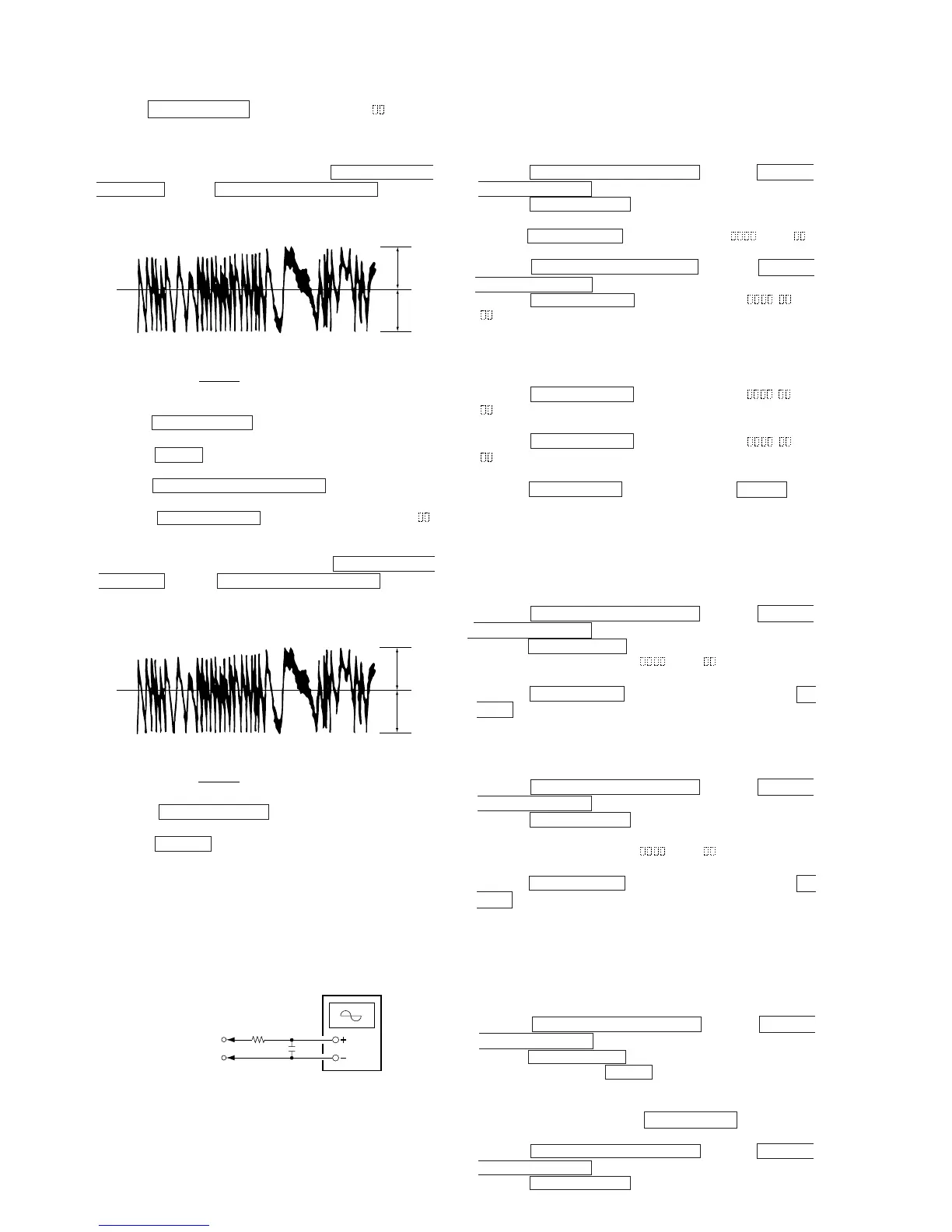
10. Observe the waveform of the oscilloscope, and check that the
specified value is satisfied. Do not press the =0/MD/CD
TUNING– button or )+/MD/CD/TUNING+ button.
(Traverse Waveform)
11. Press the ENTER/YES “R” button display “EF MO CHECK”
The disc stops rotating automatically.
12. Press the 6 (MD) button and remove the disc.
13. Load the check disc (MD) TDYS-1.
14. Press the )+/MD/CD/TUNING + button and display
“EF CD CHECK”.
15. Press the ENTER/YES “R” button and display “EFB =
CD”. Servo is imposed automatically.
16. Observe the waveform of the oscilloscope, and check that the
specified value is satisfied. Do not press the =0/MD/CD
TUNING– button or )+/MD/CD/TUNING+ button.
(Traverse Waveform)
17. Press the ENTER/YES “R” button and display “EF CD
CHECK”.
18. Press the 6 (MD) button and remove the check disc (MD)
TDYS-1.
Note 1 : MO reading data will be erased during if a recorded disc is
used in this adjustment.
Note 2 : If the traverse waveform is not clear, connect the oscillo-
scope as shown in the following figure so that it can be
seen more clearly.
5-6-4. Focus Bias Check
Change the focus bias and check the focus tolerance amount.
Checking Procedure :
1. Load a test disk (MDW-74/AU-1).
2. Press the =0/MD/CD/TUNING – button or )+/
MD/CD/TUNING + button and display “CPLAY MODE”.
3. Press the ENTER/YES “R” button twice and display “CPLAY
MID”.
4. Press the MENU/NO “R” button when “C1 = AD = ”
is displayed.
5. Press the =0/MD/CD/TUNING – button or )+/
MD/CD/TUNING + button and display “FBIAS CHECK”.
6. Press the ENTER/YES “R” button and display “ / c =
”.
The first four digits indicate the C1 error rate, the two digits
after “/” indicate ADER, and the 2 digits after “c =” indicate the
focus bias value.
Check that the C1 error is below 220 and ADER is below 2.
7. Press the ENTER/YES “R” button and display “ / b =
”.
Check that the C1 error is below 220 and ADER is below 2.
8. Press the ENTER/YES “R” button and display “ / a =
”.
Check that the C1 error is below 220 and ADER is below 2.
9. Press the MENU/NO “R” button, next press the 6 (MD) but-
ton, and remove the test disc.
5-6-5. C PLAY Checking
MO Error Rate Check
Checking Procedure :
1. Load a test disk (MDW-74/AU-1).
2. Press the =0/MD/CD/TUNING – button or )+/
MD/CD/TUNING + button and display “CPLAY MODE”.
3. Press the ENTER/YES “R” button and display “CPLAY MID”.
4. The display changes to “C1 =
AD = ”.
5. If the C1 error rate is below 80, check that ADER is below 2.
6. Press the MENU/NO “R” button, stop playback, press the 6
(MD) button, and test disc.
CD Error Rate Check
Checking Procedure :
1. Load a check disc (MD) TDYS-1.
2. Press the =0/MD/CD/TUNING – button or )+/
MD/CD/TUNING + button and display “CPLAY MODE”.
3. Press the ENTER/YES “R” button twice and display “CPLAY
MID”.
4. The display changes to “C1 = AD = ”.
5. Check that the C1 error rate is below 50.
6. Press the MENU/NO “R” button, stop playback, press the 6
(MD) button, and the test disc.
5-6-6. Self-Recording/playback Check
Prepare a continuous recording disc using the unit to be repaired
and check the error rate.
Checking Procedure :
1. Insert a recordable disc (blank disc) into the unit.
2. Press the =0/MD/CD/TUNING – button or )+/
MD/CD/TUNING + button to display “CREC MODE”.
3. Press the ENTER/YES “R” button to display the “CREC MID”.
4. When recording starts, r REC indicator lights up displayed,
this becomes “CREC (@@@@)" (@@@@ is the address), and
recording starts.
5. About 1 minute later, press the MENU/NO “R” button to stop
continuous recording.
6. Press the =0/MD/CD/TUNING – button or )+/
MD/CD/TUNING + button to display “C PLAY MODE”.
7. Press the ENTER/YES “R” button to display “C PLAY MID”.
VC
A
B
Specified value : Below 10% offset value
Offset value (%) = X 100
I
A – B
I
2 (A + B)
VC
A
B
Specified value : Below 10% offset value
Offset value (%) = X 100
I
A – B
I
2 (A + B)
330 k
Ω
Oscilloscop

 Loading...


