34
HCD-RV777D/RV888D/RV999D
0 dB=0.775 V
DECK SECTION
1. Demagnetize the record/playback head with a head
demagnetizer.
2. Do not use a magnetized screwdriver for the adjustments.
3. After the adjustments, apply suitable locking compound to the
parts adjust.
4. The adjustments should be performed with the rated power
supply voltage unless otherwise noted.
5. The adjustments should be performed in the order given in this
service manual. (As a general rule, playback circuit adjustment
should be completed before performing recording circuit
adjustment.)
6. The adjustments should be performed for both L-CH and R-
CH.
7. Switches and controls should be set as follows unless otherwise
specified.
•Test Tape
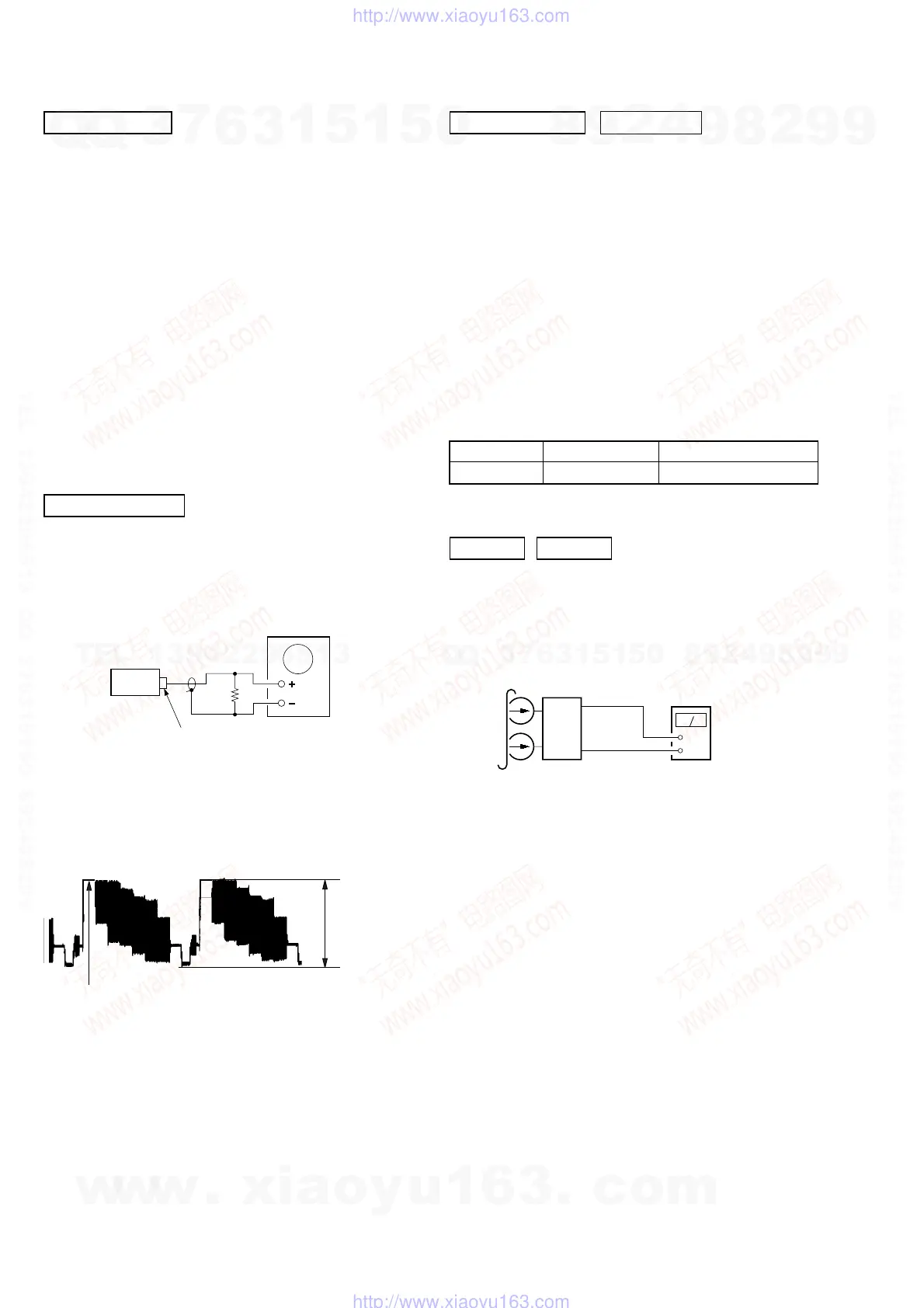
Record/Playback Head Azimuth Adjustment
Note: Perform this adjustments for both decks
Procedure:
1. Mode: Playback
Tape Signal Used for
P-4-A063 6.3 kHz, –10 dB Azimuth Adjustment
DECK A DECK B
set
MAIN board
IC101
Pin 28 (L-CH)
Pin 37 (R-CH)
MAIN board
IC101
Pin 38 (GND)
+
–
level mete
test tape
P-4-A063
(6.3 kHz, –10 dB)
SECTION 6
ELECTRICAL ADJUSTMENTS
VIDEO SECTION
oscilloscope
set
J802
VIDEO OUTPUT
75
Ω
1.00
±
0.05 Vp-p
(WHITE 100%)
Video Level Check (VIDEO BOARD)
Purpose
This adjustment is made to satisfy the NTSC standard, and if not
adjusted correctly, the brightness will be too large or small.
Procedure:
1. Connect oscilloscope to VIDEO output.
2. Load a DVD reference disc playback.
3. Check the video signal level is 1.00±0.05Vp-p.
DVD SECTION
About the dicision to pass or fail of the optical pick-up block, refer
to “DICISION TO PASS OR FAIL OF THE OPTICAL PICK-UP
BLOCK” (see page 8)
TEST DISC LIST
Use the following test disc on test mode.
LUV-P01 (CD): PART No. 4-999-032-01
TDV-520CSO (DVD-SL): PART No. J-2501-236-A
TDV-540C (DVD-DL): PART No. J-2501-235-A
Note: Do not use exiting test disc for DVD.
AUTO SERVO ADJUSTMENT
After parts related to the servo circuit (RF amplifier (IC001), DSP
(IC509), motor driver (IC501), EEPROM (IC903) so on) are
replaced, re-adjusting the servo circuit is necessary. Select “ALL”
at “1. DRIVE AUTO ADJUSTMENT” (Refer to page 8 in TEST
MODE) and adjust DVD-SL (single layer), CD and DVD-DL (dual
layer).
w
w
w
.
x
i
a
o
y
u
1
6
3
.
c
o
m
Q
Q
3
7
6
3
1
5
1
5
0
9
9
2
8
9
4
2
9
8
T
E
L
1
3
9
4
2
2
9
6
5
1
3
9
9
2
8
9
4
2
9
8
0
5
1
5
1
3
6
7
3
Q
Q
TEL 13942296513 QQ 376315150 892498299
TEL 13942296513 QQ 376315150 892498299
http://www.xiaoyu163.com
http://www.xiaoyu163.com
 Loading...