— 93 —
Pin No.
1
2
3
4
5
6
7
8
9
10
11
12
13
14
15
16
17
18
19
20
21
22
23
24
25
26
27
28
29
30
31
32
33
34
35
36
37
38
39
40
41
42
43
44
45
46
47
48
49
50
I/O
O
O
I/O
–
I/O
I
O
–
–
–
–
–
–
–
I
–
I
O
–
–
–
–
–
–
–
–
–
–
O
–
–
–
–
I
I
–
I
O
I
–
–
–
–
–
O
O
O
O
O
I
Pin name
NC
HS
IIC DATA
NC
IIC CLK
232C RX
232C TX
NC
EVDD
NC
NC
NC
NC
NC
PCK DATA
NC
PCK CLK
DISP BK
NC
NC
VPP
NC
NC
NC
NC
NC
NC
NC
UB SEL
NC
NC
NC
NC
RESET
XT1
NC
REGC
X2
X1
VSS
VDD
NC
NC
NC
PO1
PO2
PO3
R.OUT1
R.OUT2
R.IN1
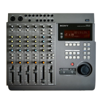
• IC300 µPD70F3033AYGF SYSTEM CONTROL
Function
Not used
Flash writer handshake signal output
IIC communication data input/output
Not used
IIC communication clock input/output
Remote terminal receiver signal (rear panel)
Remote terminal sender signal (rear panel)
Not used
Power supply to be supplied to port
Not used
Not used
Not used
Not used
Not used
PC keyboard data
Not used
PC keyboard clock
Display blanking output
Not used
Not used
Flash writer write voltage
Not used
Not used
Not used
Not used
Not used
Not used
Not used
Unbalanced/balanced input selection output
Not used
Not used
Not used
Not used
System reset signal input
Fixed at "L" (pull-down)
Not used
External connector for stabilization of the regulated output power, is connected to this pin
External main clock oscillator is connected to this pin
External main clock oscillator is connected to this pin
Ground terminal
Power supply terminal
Not used
Not used
Not used
Parallel signal output 1
Parallel signal output 2
Parallel signal output 3
Relay signal output 1
Relay signal output 2
Relay signal input 1