66
Pin No.
1
2
3
4
5
6
7, 8
9
10
11
12
13
14
15, 16
17
18
19
20
21
22, 23
24, 25
26
27
28
29
30
31
32
33
34, 35
36
37
38
39
40
41
42
I/O
I
—
I
I
—
O
—
I
I
—
I
I
O
—
I
I
I
I
I
—
—
O
I
—
—
I
—
—
I
I
—
I
I
—
I
I
I
Description
Input pin for test (Fixed at “L”)
Not used in this system (Blank terminal)
Sync mode selector input. “L”: Slave mode. “H”: Master mode. Fixed to “L”
Reset signal input from the system controller (IC800) “L”: Reset
Not used in this system (Blank terminal)
Flag output terminal for calibration. Not used in this system (Blank terminal)
Power supply (+5 V)
L/R sampling clock signal input Not used (Fixed at “L”)
Bit clock signal input of serial input/output data. Not used in this system (Fixed at “L”)
Not used in this system (Blank terminal)
L channel data input (when 8Fs, 2Fs, and FS) Not used in this system (Fixed at “L”)
R channel data input (8FS and 2FS) FSYNC input when FS Not used in this system (Fixed at “L”)
Sync flag output terminal to the input side. Not used in this system (Blank terminal)
Not used in this system (Blank terminal)
FE selection IBIT (ed-pin) “L” LR selection when “H”
Fixed at “L” in this system
64FS data (L channel data) input Not used in this system (Fixed at “L”)
64FS data (R channel data) input Not used in this system (Fixed at “L”)
64FS data input from A/D converter (IC302) (L channel data)
64FS data input from A/D converter (IC302) (R channel data)
Ground
Ground (For oscillator circuit)
FE clock signal output to A/D converter (IC302) (128FS)
Master clock signal input to D/A converter (IC502) (256FS)
Power supply (+5 V) (For oscillator circuit)
Not used in this system (Blank terminal)
Input terminal to set the input data word length during 64 FS. “L: 1 bit, “H”: 4 bits. (Fixed at “L”)
Not used in this system (Blank terminal)
Ground
Input terminal to set the scaling amount during 64 FS. “L: x5, “H”: x4. (Fixed at “L”)
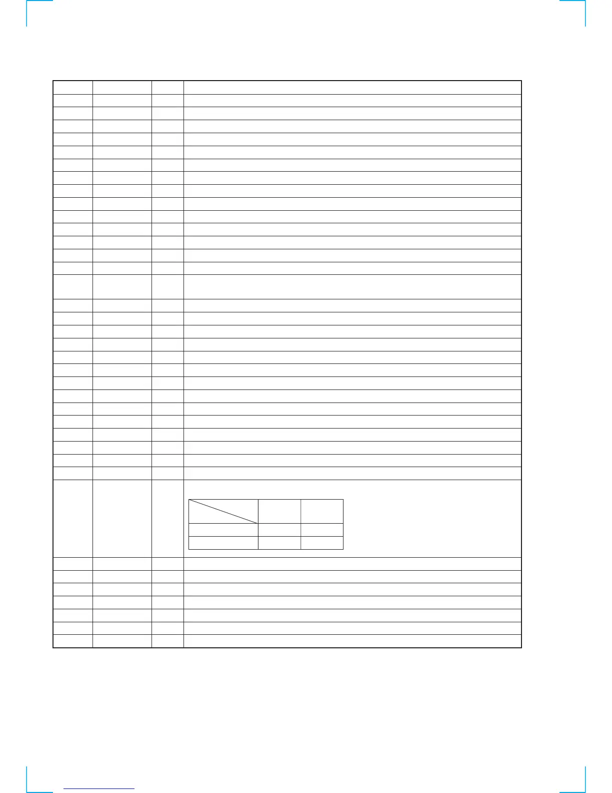
Input terminal to set the input sampling frequency. (Fixed both terminals to “L” = 64 FS)
Not used in this system (Blank terminal)
Input terminal to set the dizzer mode. “L: OFF, “H”: ON. (Fixed at “H”)
Input terminal to set the frequency compensation function. “L: OFF, “H”: ON. (Fixed at “H”)
Power supply terminal (+ 5V)
Mode data input Not used in this system (Fixed at “H”)
Serial data shift clock signal input Not used in this system (Fixed at “H”)
Serial data shift latch pulse input Not used in this system (Fixed at “H”)
Pin Name
TEST
NC
SYNC
INIT
NC
CLFG
VDD
LRKI
BKI
NC
DLI
DRI
IFLG
NC
LR
AL2
AR2
AL1
AR1
VSS
VSS
FCLK
MCLK
VDD
NC
IBIT
NC
VSS
SCALE
ISET1,ISET2
NC
DITH
BOOST
VDD
MODE
SHIFT
LATCH
• AD BOARD IC301 CXD8512Q (DIGITAL FILTER)
ISEL2
“H”
“L”
ISEL1
“H”
8FS
2FS
“L”
FS
64FS
 Loading...