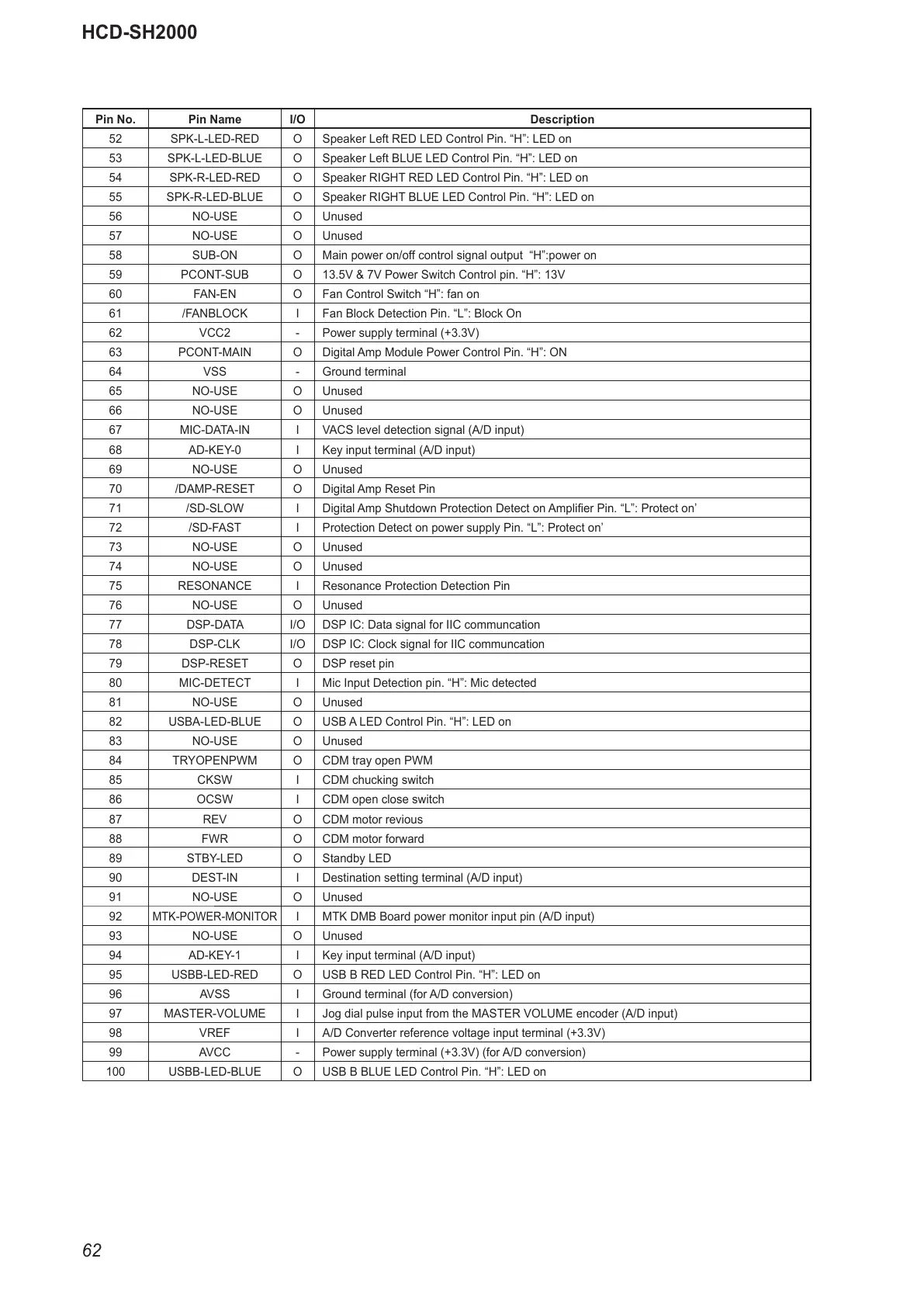
HCD-SH2000
62
Pin No. Pin Name I/O Description
52 SPK-L-LED-RED O Speaker Left RED LED Control Pin. “H”: LED on
53 SPK-L-LED-BLUE O Speaker Left BLUE LED Control Pin. “H”: LED on
54 SPK-R-LED-RED O Speaker RIGHT RED LED Control Pin. “H”: LED on
55 SPK-R-LED-BLUE O Speaker RIGHT BLUE LED Control Pin. “H”: LED on
56 NO-USE O Unused
57 NO-USE O Unused
58 SUB-ON O Main power on/off control signal output “H”:power on
59 PCONT-SUB O 13.5V & 7V Power Switch Control pin. “H”: 13V
60 FAN-EN O Fan Control Switch “H”: fan on
61 /FANBLOCK I Fan Block Detection Pin. “L”: Block On
62 VCC2 - Power supply terminal (+3.3V)
63 PCONT-MAIN O Digital Amp Module Power Control Pin. “H”: ON
64 VSS - Ground terminal
65 NO-USE O Unused
66 NO-USE O Unused
67 MIC-DATA-IN I VACS level detection signal (A/D input)
68 AD-KEY-0 I Key input terminal (A/D input)
69 NO-USE O Unused
70 /DAMP-RESET O Digital Amp Reset Pin
71 /SD-SLOW I Digital Amp Shutdown Protection Detect on Amplifi er Pin. “L”: Protect on’
72 /SD-FAST I Protection Detect on power supply Pin. “L”: Protect on’
73 NO-USE O Unused
74 NO-USE O Unused
75 RESONANCE I Resonance Protection Detection Pin
76 NO-USE O Unused
77 DSP-DATA I/O DSP IC: Data signal for IIC communcation
78 DSP-CLK I/O DSP IC: Clock signal for IIC communcation
79 DSP-RESET O DSP reset pin
80 MIC-DETECT I Mic Input Detection pin. “H”: Mic detected
81 NO-USE O Unused
82 USBA-LED-BLUE O USB A LED Control Pin. “H”: LED on
83 NO-USE O Unused
84 TRYOPENPWM O CDM tray open PWM
85 CKSW I CDM chucking switch
86 OCSW I CDM open close switch
87 REV O CDM motor revious
88 FWR O CDM motor forward
89 STBY-LED O Standby LED
90 DEST-IN I Destination setting terminal (A/D input)
91 NO-USE O Unused
92
MTK-POWER-MONITOR
I MTK DMB Board power monitor input pin (A/D input)
93 NO-USE O Unused
94 AD-KEY-1 I Key input terminal (A/D input)
95 USBB-LED-RED O USB B RED LED Control Pin. “H”: LED on
96 AVSS I Ground terminal (for A/D conversion)
97 MASTER-VOLUME I Jog dial pulse input from the MASTER VOLUME encoder (A/D input)
98 VREF I A/D Converter reference voltage input terminal (+3.3V)
99 AVCC - Power supply terminal (+3.3V) (for A/D conversion)
100 USBB-LED-BLUE O USB B BLUE LED Control Pin. “H”: LED on