18
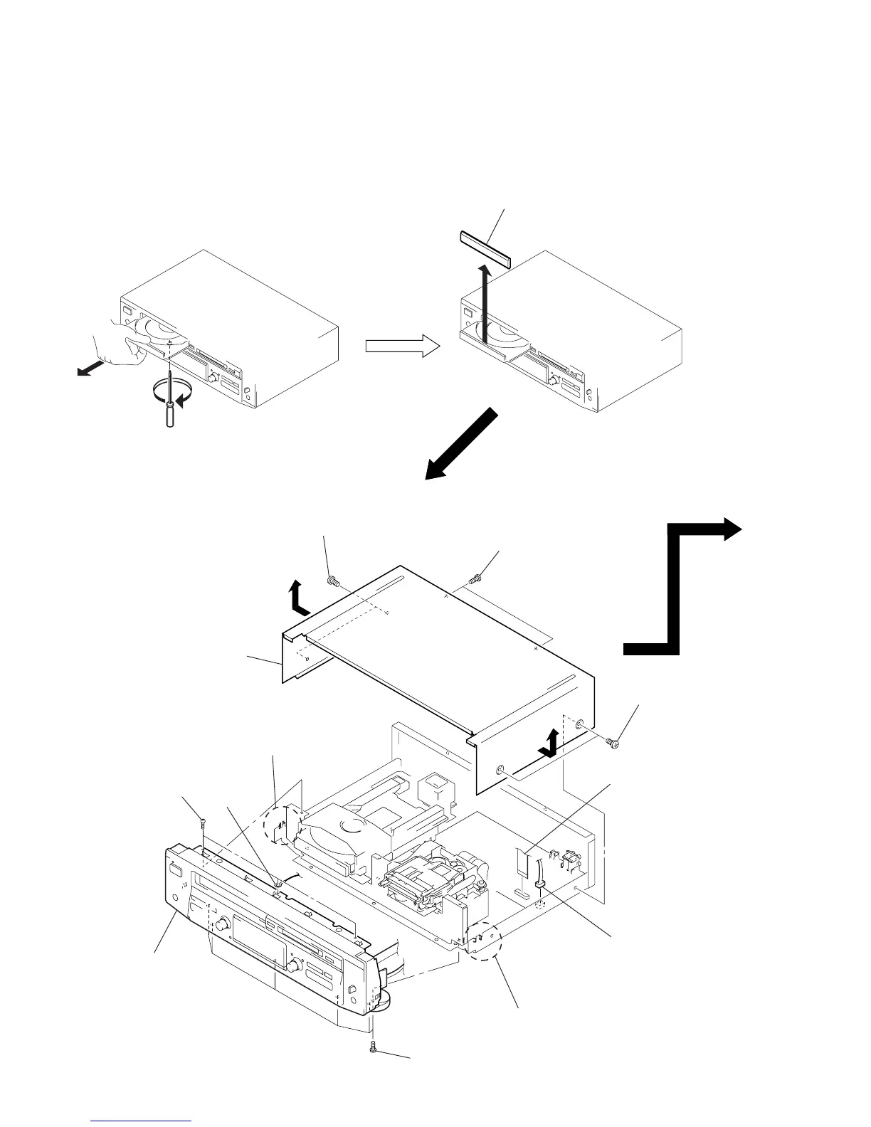
LOADING PANEL
In removing the front panel with the power not supplied,
insert a flat-blade screwdriver into a hole at the bottom of loading section and rotate it counterclockwise.
Then, draw out the disc table and remove the loading panel.
COVER, FRONT PANEL SECTION
Note: Follow the disassembly procedure in the numerical order given.
SECTION 3
DISASSEMBLY
2
1
3
Remove the loading panel
to direction of the arrow.
1
two screws
(case3 TP2)
1
two screws
(case3 TP2)
1
two screws
(case3 TP2)
3
wire (flat type) (19 core