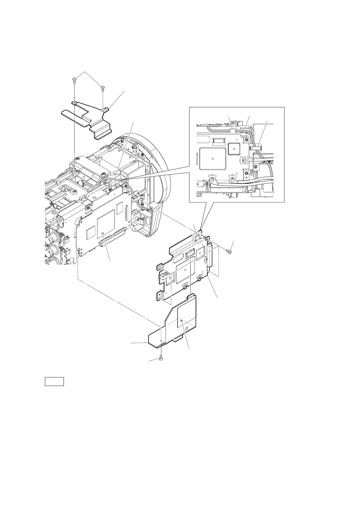
5. Remove the four screws to detach the VPR spreader assembly.
Harness
Precision screws
(P2 x 4)
Out side radiation plate
VPR spreader assembly
TOP radiation sheet metal
Precision screws
(P2 x 4)
(a)
(b)
Precision screws
(P2 x 4)
Claw
Boss
Hole
Harness
Clamp
Claw
Note
• When installing the VPR spreader assembly, arrange the harness as shown in the figure.
• When installing the outside radiation plate, fit the boss with the hole.
• When installing the top radiation sheet metal, tighten the screws (a) to (b) in this order.
6. Disconnect the three coaxial cables from the three connectors on the VPR-124 board.
PMW-300
2-43