Do you have a question about the Sony PS-FL1 and is the answer not in the manual?
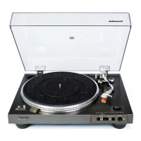
Details key specifications for the turntable's platter, motor, drive, speed, and tonearm characteristics.
Components identified by shading and mark A are critical for safe operation; replace with SONY parts.
Les composants critiques identifiés par trame et marque A sont critiques pour la sécurité ; remplacer par pièces SONY.
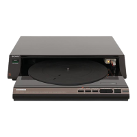
The turntable module slides out for easy access, allowing other components to be placed on top.
A microcomputer controls the turntable, tonearm, and module movement for automated operation.
Automatic record play, stylus up/down, and record size selection via photo sensor.
Features Sony's BSL motor for low noise, smooth operation, and quick start capabilities.
An optical sensor detects record return point, allowing for light tracking force.
Enables synchronized recording between turntable and cassette deck via remote control.
Allows remote control of power, play, stop, and stylus movement using an optional remote controller.
Details voltage and power requirements for different regional models (US, AEP, UK, E).
Steps to prevent static damage when replacing MOS ICs, including storage and handling methods.
Steps for removing transit screws, unpacking, and connecting the unit to power.
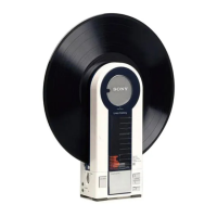
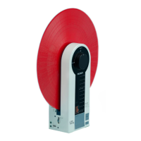
Instructions on using the OPEN/CLOSE button to access the turntable.
States that the cartridge is factory-installed on the PS-FL1C and replacement is usually not necessary.
Guidelines on cartridge weight compatibility and connecting lead wires to cartridge pins.
Steps to secure the tonearm, plug in the cartridge shell, and insert the counterweight.
Procedure for balancing the tonearm to ensure accurate stylus tracing and proper tracking force.
How to set the correct tracking force for the stylus using the tracking force ring.
How to adjust the anti-skating compensator to cancel forces that drive the tonearm toward the center.
Final steps after tonearm adjustment, including replacing the top plate and securing screws.
Steps before making connections, including turning off the amplifier and ensuring firm jack insertion.
Instructions for connecting the turntable's audio and ground wires to the amplifier.
Steps before playing a record, including placing it on the platter and setting the amplifier.
How the auto record size selection works and the steps for starting playback.
How to begin record play at a specific point on the record.
How to lift/lower the stylus during play (ARM LIFTER) and stop playback.
How to activate and deactivate the repeat play feature.
How to connect the turntable and cassette deck for synchronized recording.
Describes turntable and cassette deck operations during synchronized playback.
Step-by-step guide for detaching the old stylus and installing a new one.
Instructions on cleaning the stylus using a soft brush or fluid cleaner.
How to clean the turntable cabinet and rubber mat using appropriate methods.
Notes that the turntable requires no periodic lubrication as the motor shaft is factory-lubricated.
Explains the BSL DC servo motor, FG board detection method, and magnetization poles.
Cautions for safely turning the turntable unit upside down to prevent damage.
Steps for removing the control panel, various boards, and the power switch board.
Instructions for removing the turntable sheet and the record sensor (A) board.
Notes on identifying motors and maximum gear diameter for mounting.
Illustrates contact slider positions for common, play, drop point, and rest states.
Shows correct brake shoe position relative to the brake drum when the tonearm is on the arm rest.
Important notes regarding turntable rotation and module slide motor behavior during adjustments.
Steps to adjust the stylus drop-point for accurate record play, including test record usage.
How to adjust the shell's horizontal balance to ensure a slant of less than 0.3mm.
Procedure to set the stylus height, ensuring correct distance from the record.
Procedure to adjust the brake drum position so its edge aligns with the brake felt.
Procedure to adjust the tonearm return position for proper auto-return count.
Detailed steps for adjusting gain and offset using an oscilloscope and specific test points.
Detailed schematic for the main board, including ICs, transistors, and signal paths.
Schematics for the power supply, power switch, and FG board.
Schematics for switch, record size, interrupter, and remote control boards.
Schematics for the phono board, motor drive, and size detection circuits.
Schematics for power supply, switch boards, and record size detection.
Exploded view of the main turntable assembly with numbered parts.
Exploded views of sub-assemblies like power transformer and circuit boards.
Further exploded view of the main turntable assembly with numbered parts.
Additional exploded views of sub-assemblies and regional variations.
Detailed exploded view of the turntable assembly showing part placement.
Detailed exploded views of sub-assemblies and regional models.
Exploded view illustrating mechanical parts and their arrangement.
Exploded view showing the motor M101 and the gear train components.
Exploded view of the tonearm, lifter plate, and associated control mechanisms.
List of general parts for the turntable, categorized by number and description.
Continues the list of general parts with part numbers and descriptions.
Lists electrical parts including diodes, ICs, jacks, motors, lamps, and solenoids.
Lists resistors, potentiometers, switches, transformer, and oscillator part numbers.
Lists electrolytic capacitor part numbers by capacitance and voltage rating.
Lists ceramic capacitor part numbers by capacitance and voltage rating.
Lists Mylar capacitor part numbers by capacitance and voltage rating.
Lists Tantalum capacitor part numbers by capacitance and voltage rating.
Explains screw types, sizes, and their common reference designations.
Explains nuts, washers, and retaining rings and their reference designations.