19
RCD-W3
Procedure :
1. Connect oscilloscope to IC402 wg pin (TE) and IC402 wk pin
(VC).
2. Turned Power switch on.
3. Load a disc (YEDS-18) and playback the number five track.
4. Press the X button. (Becomes the 1 track jump mode.)
5. Confirm that the level B and A (DC voltage) on the oscillo-
scope waveform.
CD SECTION
Note :
1. CD Block is basically designed to operate without adjustment.
Therefore, check each item in order given.
2. Use YEDS-18 disc unless otherwise indicated.
3. Use an oscilloscope with more than 10MΩ impedance.
4. Clean the object lens by an applicator with neutral detergent
when the signal level is low than specified value with the fol-
lowing checks.
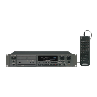
RF Level Check
Procedure :
1. Connect oscilloscope to IC402 eh pin (RFAC) and IC402 wk
pin (VC).
2. Turned Power switch on.
3. Load a disc (YEDS-18) and playback.
4. Confirm that oscilloscope waveform is clear and check RF sig-
nal level is correct or not.
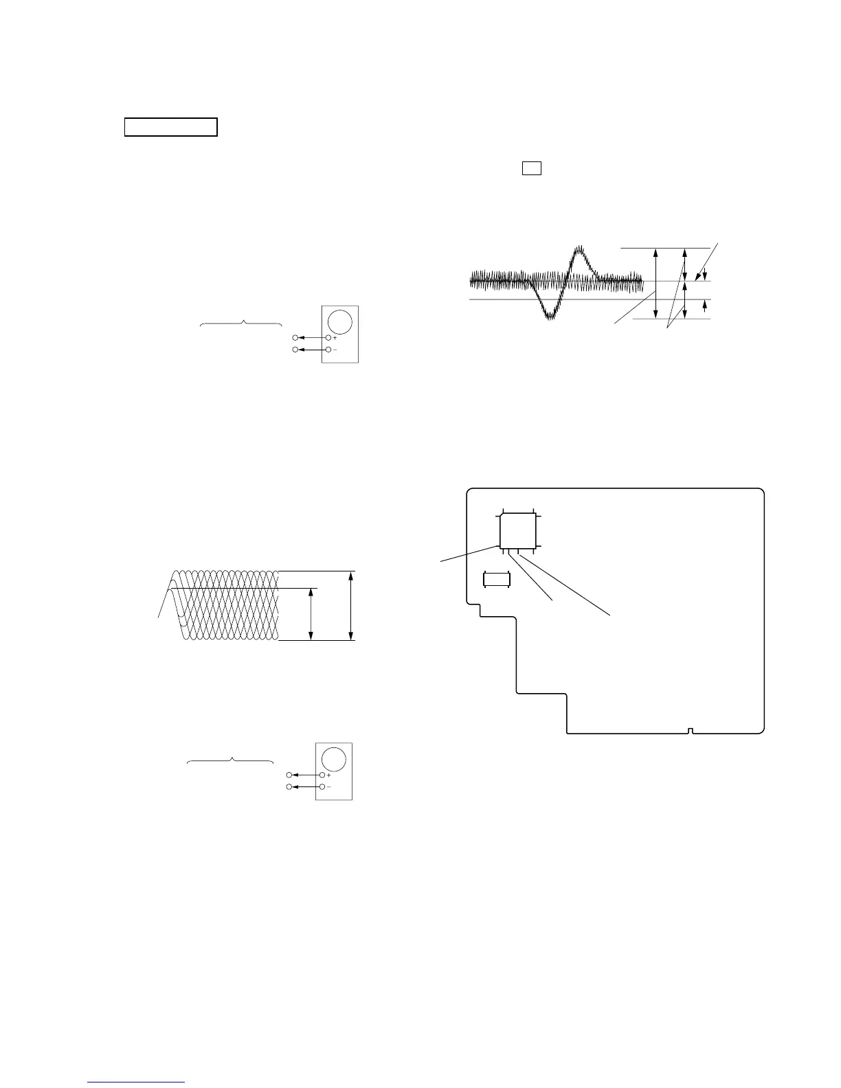
IC402 ehpin(RFAC)
IC402 wkpin(VC)
BD-R board
oscilloscope
SERVO Check
Note : Clear RF signal waveform means that the shape “ ◊ ” can be clearly
distinguished at the center of the waveform.
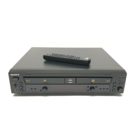
E-F Balance (1 Track jump) Check
RF signal waveform
VOLT/DIV : 200mV
TIME/DIV : 500ns
3T= 0.55
±
0.07Vp-p
11T= 0.90
±
0.13Vp-p
3T
11T
IC402
wg
pin(TE)
IC402
wk
pin(VC)
BD-R board
oscilloscop
 Loading...