47
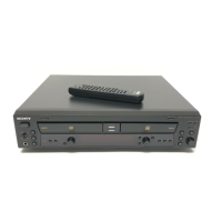
RCD-W3
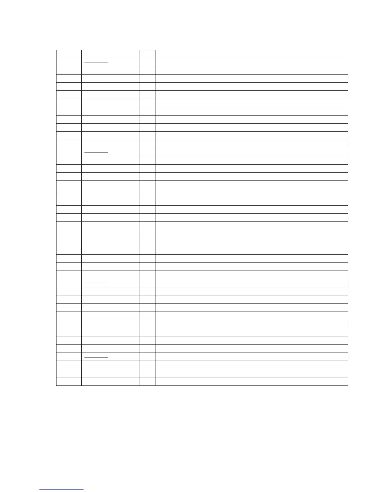
Pin No. Description
Pin Name I/O
58 — Not used (open)
59 PWR CTL O System power ON/OFF signal output
60 PWR MUTE O Headphone audio mute signal output
61 — Not used (open)
62 /STBY I Not used (connected to 5V)
63 /RESET I System reset signal input
64 PWR FAIL IN I Power monitor input
65 GND — Ground
66 EXTAL I Connected to the crystal oscillator (20MHz)
67 XTAL O Connected to the crystal oscillator (20MHz)
68 5V — Power supply
69 to 72 — Not used (open)
73 MD0 I Not used (connected to 5V through resister)
74 MD1 I Not used (connected to 5V through resister)
75 MD2 I Mode input (for check)
76 5VA — Power supply
77 VREF (4V) I A/D reference voltage input (+4V)
78 KEY IN0 I Key input 0 (A/D port)
79 KEY IN1 I Key input 1 (A/D port)
80 KEY IN2 I Key input 2 (A/D port)
81 TE/FE I TE/FE signal input
82 SLD ERR I Tracking drive monitor input
83 1.35/AUD I Audio level /sled reference voltage monitor input
84 SLD CTL A O Sled motor control signal output
85 SLD CTL B O Sled motor control signal output
86 AGND — Ground
87 SPD G UP O Motor speed control signal output
88 — Not used (open)
89 SCOR I Input a high signal when either subcode sync S0 or S1 is detected
90 SLDIN SW I Sled inner side detect signal input
91 — Not used (open)
92 GND — Ground
93 COUT I/O Track control signal input/output
94 SQCK O SQSO readout clock output to CXD3023
95 FG I Spindle Frequency Generator signal input from M63021FP
96 SCLK O SENS readout clock output
97 — Not used (open)
98 AS PROG I Not used (pull up)
99 AS FCS/TRK O TE/FE select signal output
100 REMO IN I Remote commander signal input

 Loading...