17
KDL-40XBR4/40XBR5/46XBR4/46XBR5
KDL-40XBR4/40XBR5/46XBR4/46XBR5
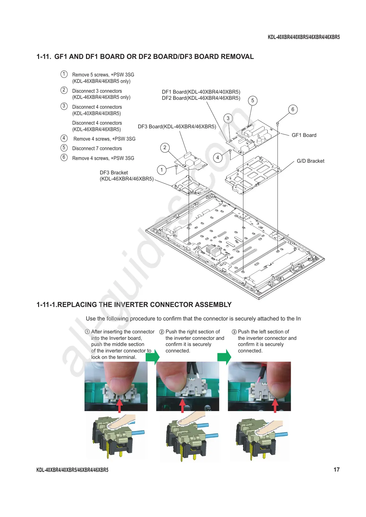
1-11. GF1 AND DF1 BOARD OR DF2 BOARD/DF3 BOARD REMOVAL
1
Remove 5 screws, +PSW 3SG
(KDL-46XBR4/46XBR5 only)
2
Disconnect 3 connectors
(KDL-46XBR4/46XBR5 only)
3
Disconnect 4 connectors
(KDL-40XBR4/40XBR5)
Disconnect 4 connectors
(KDL-46XBR4/46XBR5)
4
Remove 4 screws, +PSW 3SG
5
Disconnect 7 connectors
6
Remove 4 screws, +PSW 3SG
1-11-1. REPLACING THE INVERTER CONNECTOR ASSEMBLY
1
2
4
3
6
5
G/D Bracket
GF1 Board
DF3 Bracket
(KDL-46XBR4/46XBR5)
DF3 Board(KDL-46XBR4/46XBR5)
DF1 Board(KDL-40XBR4/40XBR5)
DF2 Board(KDL-46XBR4/46XBR5)
1
After inserting the connector
into the Inverter board,
push the middle section
of the inverter connector to
lock on the terminal.
Push the right section of
the inverter connector and
confirm it is securely
connected.
Push the left section of
the inverter connector and
confirm it is securely
connected.
2 3
Use the following procedure to confirm that the connector is securely attached to the In
All manuals and user guides at all-guides.com
all-guides.com