7-2
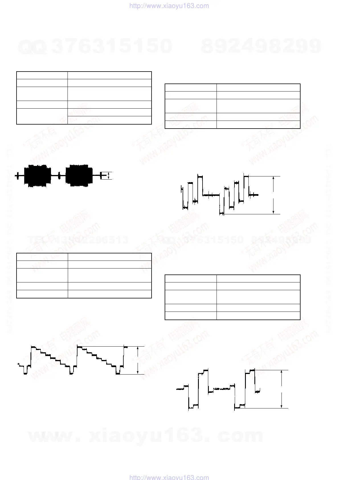
3. S-Video Output S-C Check
<Purpose>
This check confirms that the S-video output S-C conforms to the
PAL standard. If it adjusted incorrectly, the playback color will not
be too dark or too thin.
Mode PLAY
Signal 100% Color bars
Test point S-VIDEO OUTPUT (S-C) connector
(terminated in 75Ω)
Instrument Oscilloscope
Specification PAL: 300 mV±30 mVp-p
NTSC: 286mV±30 mVp-p
Check method:
1) Insert the PAL/NTSC reference disc and play back the 100%
color bars.
2) Confirm that the burst signal level is 300 mV±30 mVp-p.
Fig. 7-3
4. Component Video Output Y Check
<Purpose>
This check confirms that the component Y signal output has the
rated amplitude. If this signal level is not correct, brightness of the
video signal will not be too dark or too thin when the COMPONENT
connector output signal is connected to a projector having
COMPONENT input.
Mode PLAY
Signal 100% Color bars
Test point COMPONENT VIDEO OUT (Y)
connector (terminated in 75Ω)
Instrument Oscilloscope
Specification 1.0 V±0.07Vp-p
Check method:
Note 1: Do not set RGB OUT to ON.
Note 2: Do not connect the HDMI OUT.
1) Insert the PAL/NTSC reference disc and play back the 100%
color bars.
2) Confirm that the Y signal level is 1.0 V±0.07 Vp-p.
Fig. 7-4
5. Component Video Output B-Y (Pb) Check
<Purpose>
This check confirms that the B-Y signal of the component video
conforms to the PAL/NTSC standard. If this signal level is not
correct, color of the video signal will have different color when the
COMPONENT connector output signal is connected to a projector
having COMPONENT input.
Mode PLAY
Signal 100% Color bars
Test point COMPONENT VIDEO OUT (Pb)
connector (terminated in 75Ω)
Instrument Oscilloscope
Specification 700 mV±50 mVp-p
Check method:
Note 1: Do not set RGB OUT to ON.
Note 2: Do not connect the HDMI OUT.
1) Insert the PAL/NTSC reference disc and play back the 100%
color bars.
2) Confirm that the burst signal level is 700 mV±50 mVp-p.
Fig. 7-5
6. Component Video Output R-Y (Pr) Check
<Purpose>
This check confirms that the R-Y signal of the component video
conforms to the PAL/NTSC standard. If this signal level is not
correct, color of the video signal will have different color when the
COMPONENT connector output signal is connected to a projector
having COMPONENT input.
Mode PLAY
Signal 100% Color bars
Test point COMPONENT VIDEO OUT (Pr)
connector (terminated in 75Ω)
Instrument Oscilloscope
Specification 700 mV±50 mVp-p
Check method:
Note 1: Do not set RGB OUT to ON.
Note 2: Do not connect the HDMI OUT.
1) Insert the PAL/NTSC reference disc and play back the 100%
color bars.
2) Confirm that the burst signal level is 700 mV±50 mVp-p.
Fig. 7-6
NTSC: 286mV
±
30 mVp-
PAL: 300 mV
±
30 mVp-p
1.0
±
0.07Vp-p
700
±
50 mVp-p
700
±
50 mVp-p
w
w
w
.
x
i
a
o
y
u
1
6
3
.
c
o
m
Q
Q
3
7
6
3
1
5
1
5
0
9
9
2
8
9
4
2
9
8
T
E
L
1
3
9
4
2
2
9
6
5
1
3
9
9
2
8
9
4
2
9
8
0
5
1
5
1
3
6
7
3
Q
Q
TEL 13942296513 QQ 376315150 892498299
TEL 13942296513 QQ 376315150 892498299
http://www.xiaoyu163.com
http://www.xiaoyu163.com