– 3 –
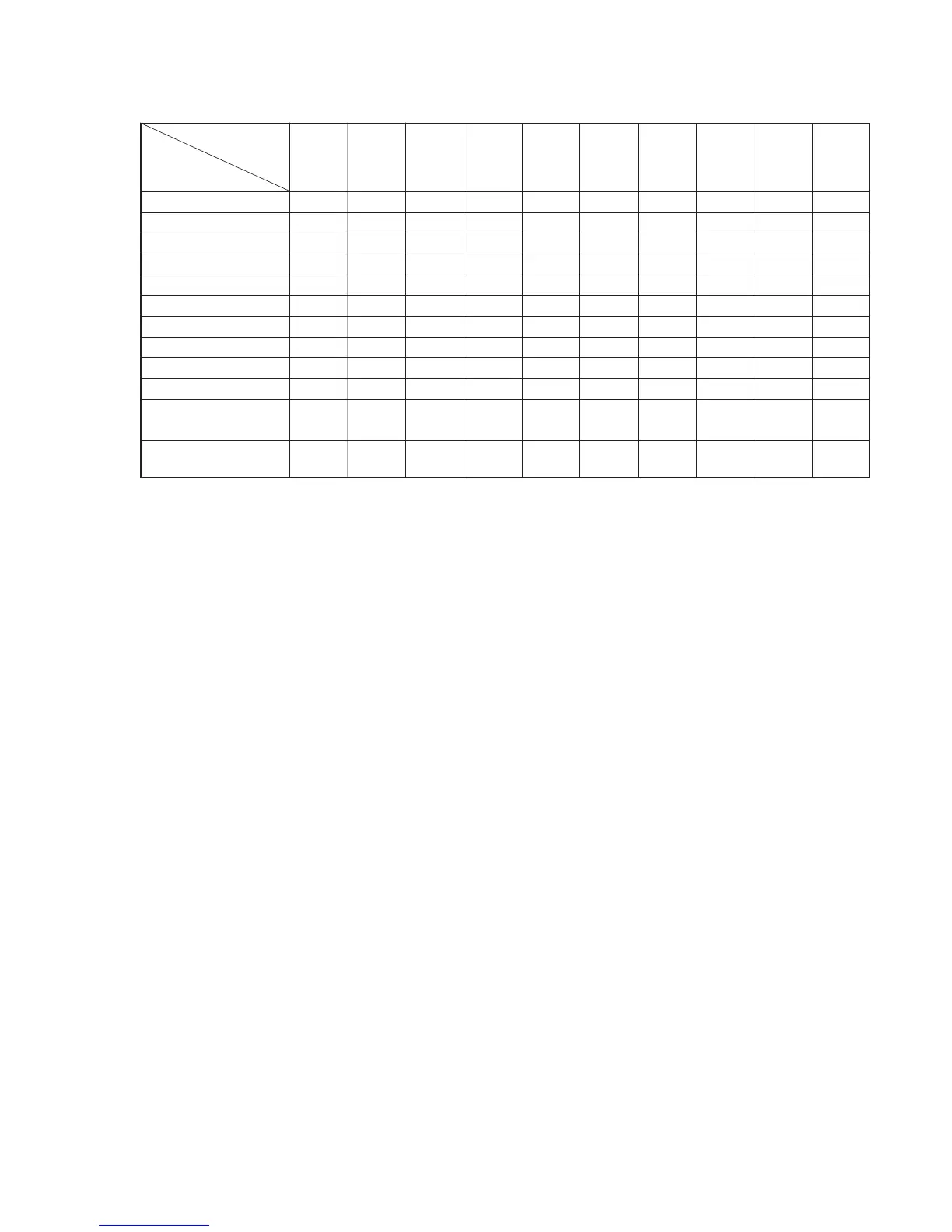
SLV- E727VC/
E730NC/
E580EE E580EG E630AE E630NP
E730NP/ E730B/ E730EX/
E730VP/ E780EE
E780EG/
E730VC/ E735B E730UX
E735NC
E780EN
FEATURE E735VC
SECAM (REC/PB) g/g
ME-SECAM (REC/PB) g/gg/gG/gg/gg/g
Hi-Fi STEREO gggggggg
SIMULATED STEREO g
FRONT IN g (COVER) gg (COVER) g
AUDIO OUT 2 gggg
LINE 2 OUT g (mono×2) g
EUR IN (2nd) gg
C+ (2nd) g (SW, IN) g (SW, C+) g (SW, C+) g (SW, C+) g (SW, C+) g (SW, IN)
RF OUT SYSTEM K/G K/G G G G L/G I G K/G K/G
CLICK SHUTTLE
gg
(JOG)
REMOTE COMMANDER
V224C V224 V220B V220B V223 V223B V223A V223 V221D V223
RMT-
• Feature Difference
SAFETY CHECK-OUT
1. Check the area of your repair for unsoldered or poorly-sol-
dered connections. Check the entire board surface for solder
splashes and bridges.
2. Check the interboard wiring to ensure that no wires are
“pinched” or contact high-wattage resistors.
3. Look for unauthorized replacement parts, particularly transis-
tors, that were installed during a previous repair. Point them
out to the customer and recommend their replacement.
After correcting the original service problem, perform the following
safety checks before releasing the set to the customer:
4. Look for parts which, though functioning, show obvious signs
of deterioration. Point them out to the customer and recom-
mend their replacement.
5. Check the B+ voltage to see it is at the values specified.
SAFETY-RELATED COMPONENT WARNING!!
COMPONENTS IDENTIFIED BY MARK ! OR DOTTED
LINE WITH MARK ! ON THE SCHEMATIC DIAGRAMS
AND IN THE PARTS LIST ARE CRITICAL TO SAFE
OPERATION. REPLACE THESE COMPONENTS WITH
SONY PARTS WHOSE PART NUMBERS APPEAR AS
SHOWN IN THIS MANUAL OR IN SUPPLEMENTS PUB-
LISHED BY SONY.