5-3
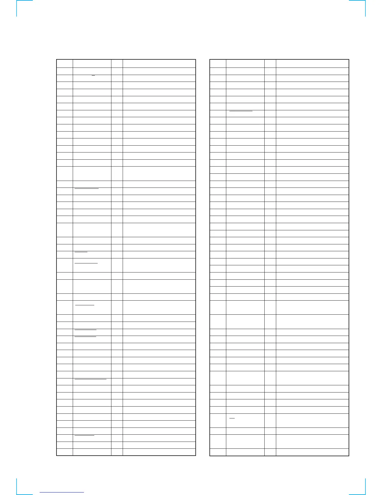
5-6. SERVO/SYSTEM CONTROL MICROPROCESSOR PIN FUNCTIONS
(MA-359 BOARD IC160)
Pin No.
1
2
3
4
5
6
7
8
9
10
11
12
13
14
15
16
17
18
19
20
21
22
23
24
25
26
27
28
29
30
31
32
33
34
35
36
37
38
39
40
41
42
43
44
45
46
47
48
49
50
Pin Name
RF SWP
AF REC P
N.C
QVD
AUTO PRESET
FE ON
SW1
N.C
CAM 2
N.C
TA MUTE
SECAM DET
N.C
SECAM MIX
CIN (REC PRF)
AV CONT
SECAM ON
MODE 4
MODE 3
MODE 2
MODE 1
ENV SW
S IN 0
S OUT 0
S CLK
ASURA CS
SRVO
CAP TRQ PWM
C + DET
CAP RVS
A MUTE
T/E LED
CAP STOP
FULL ERS
N.C
SDA 0
N.C
SCL 0
MP
ASURA RESET
V SS
XTAL
EXTAL
N.C
DRM PG
DRM FG
CAP FG
DNR RST
FRONT SEL
I CONT
I/O
O
O
O
O
O
O
O
I
O
I
I
I
O
I
I
I
I
I
I
O
I
I
O
O
O
O
O
O
O
I/O
I/O
—
I
—
O
I
—
I
I
I
—
—
—
Function
RF switching pulse output.
“H” when HiFi audio REC.
Not used.
Quasi VD pulse output.
“H” during auto preset.
Flying erase ON/OFF.
BG/L control signal
Not used.
Cam motor control.
Not used.
Tuner audio mute. H: Mute
Not used.
Not used.
Not used.
Erasing protection tab, cassette in
detection signal input.
Not used.
Cam encoder signal input.
Cam encoder signal input.
Cam encoder signal input.
Cam encoder signal input.
Video envelope mode detect signal
(SP or EP)
Serial communication signal.
Serial communication signal.
Serial communication signal.
Servo/system control microcomputer
chip select signal.
Not used.
PWM output for capstan torque
control.
Not used.
Capstan reverse control “L” when
reverse.
“H” when audio mute.
Tape top /end sensors driver.
Capstan stop signal output.
Full erase control.
Not used.
Serial communication data.
Not used.
Serial communication clock.
Ground.
System reset signal.
Ground.
System clock (16 MHz).
System clock (16 MHz).
Not used.
Drum PG input.
Drum FG input.
Capstan FG input.
NICOL control signal out.
Cable box control signal out.
Forced mono.
Pin No.
51
52
53
54
55
56
57
58
59
60
61
62
63
64
65
66
67
68
69
70
71
72
73
74
75
76
77
78
79
80
81
82
83
84
85
86
87
88
89
90
91
92
93
94
95
96
97
98
99
100
Pin Name
SW2
AVSS
AV re f
AVDD
NTPB SW
AV ADJ
FOLLW TV
N.C
AF ENV
RF ENV
T SENS
S SENS
N.C
AMP VSS
CTL HEAD (–)
CTL HEAD (+)
HEADL (+)
HEADL (–)
CTL F AMP (+)
CTL F AMP (–)
CTL GND
CTL S AMPI
CTL F AMPO
AMP VDD
CTL OUT
S REEL FG
T REEL FG
CAP DA
DRM DA
N.C
N.C
VSYNC
N.C
24 V_CONT
18 V_CONT
N.C
N.C
VSS
VDD
5V
N.C
FAST SEARCH
HA SWP
POWER SAVE CONT 1
POWER SAVE C+
MOD CONT
SP/LP
TV/VTR
STEP PLS
AF SWP
I/O
O
—
I
I
I
I
—
—
I
I
I
I
I
—
I/O
I/O
O
O
I
I
O
I
O
I
O
I
I
O
O
—
I
O
O
—
I
I
O
O
O
O
O
O
O
O
O
O
Function
Not used.
Ground.
D5V
D5V
Ground.
Adjustment mode.
Ground.
Ground.
HiFi audio playback signal envelope.
Video playback signal envelope.
Take-up end sensor.
Supply end sensor.
Not used.
Ground.
CTL signal I/O.
CTL signal I/O.
CTL signal.
CTL signal.
CTL first AMP input.
CTL first AMP input.
Ground.
CTL second AMP input.
CTL first AMP output.
5 V.
Control signal output for check pin.
Supply reel FG input.
Take-up reel FG input.
Capstan error D/A output.
Drum error D/A output.
UNSW 5 V.
Ground.
Composite sync signal input.
Not used.
24 V control, when the high speed
mode.
18 V control, when the high speed
mode.
Not used.
Not used.
Ground.
D5V
D5V
Not used.
Switching signal for capacitor on
CTL(X).
Head AMP SWP.
Not used.
Not used.
Tuner modulation out control signal.
Tape speed mode control signal “L”
when SP mode.
Not used.
Step pulse “H” when capstan step
driving.
AF switching pulse output.