6-5
2-5-4. DNR Y Level Adjustment (NR-27 board)
(SLV-SF99 model only. (Except B model) )
[Adjustment purpose]
Adjust the Y level during DNR ON.
Mode Playback
Signal Alignment tape: SP mode color bar
portion
Measurement Point CN001 9 pin (DNR Y)
Measuring Instrument Oscilloscope
Adjusting element RV002
Specified Value A=2.0 ± 0.2V
Switch setting:
DNR ..................................................... ON
[Adjusting method]
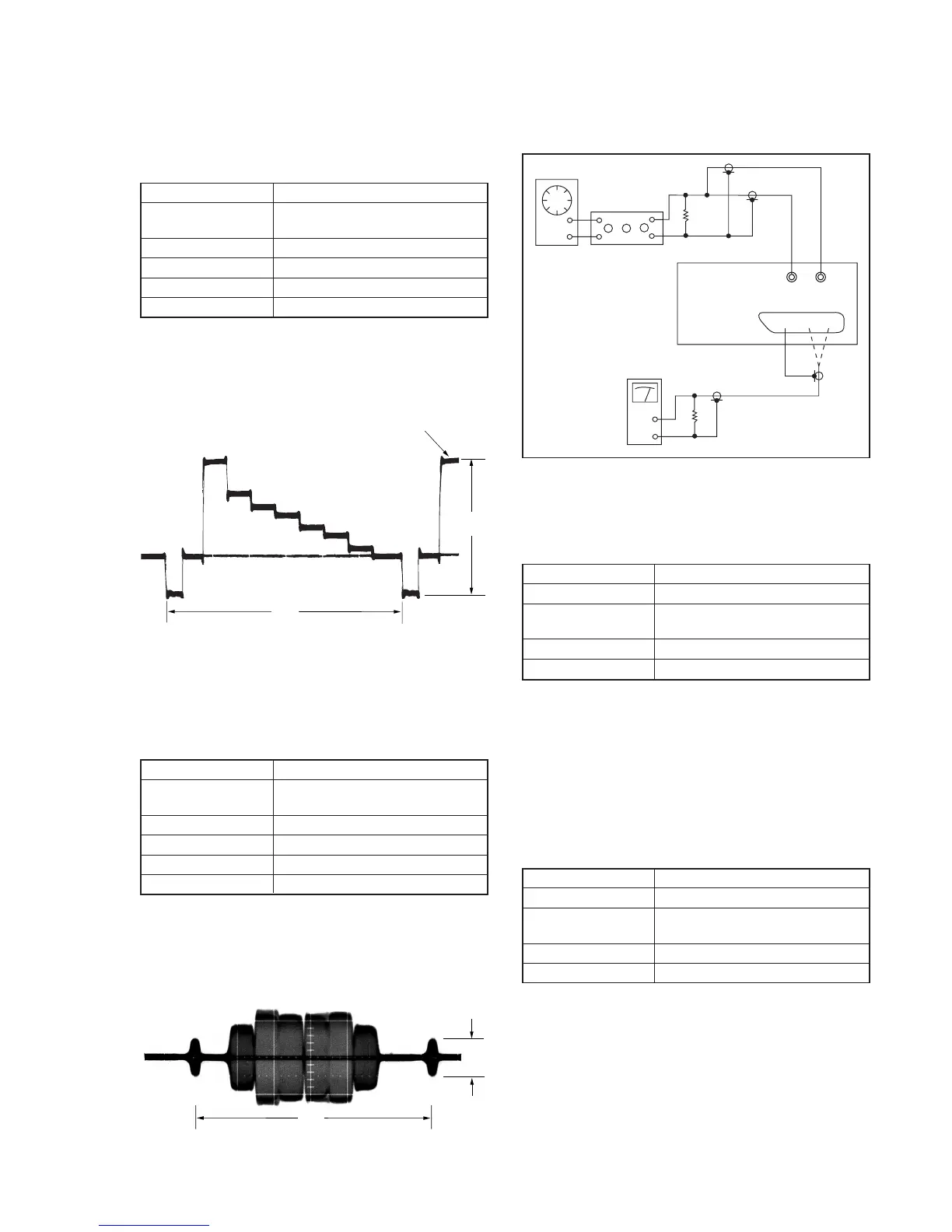
1) Adjust the Y signal level (A) to the specified value with RV002.
Fig. 6-2-7.
2-5-5. DNR C Level Adjustment (NR-27 board)
(SLV-SF99 model only. (Except B model) )
[Adjustment purpose]
Adjust the chroma level during DNR ON.
Mode Playback
Signal Alignment tape: SP mode color bar
portion
Measurement Point CN001 5 pin (DNR C)
Measuring Instrument Oscilloscope
Adjusting element RV001
Specified Value A=600 ± 70mV
Switch setting:
DNR ..................................................... ON
[Adjusting method]
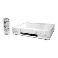
1) Adjust the burst signal level (A) to the specified value with
RV001.
Fig. 6-2-8.
2-6. AUDIO SYSTEM ADJUSTMENT
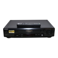
[Connecting Instruments]
Fig. 6-2-9.
2-6-1. Hi-Fi Audio System Check
2-6-1-1. E-E Output Level Check
[Adjustment purpose]
Confirm that the E-E audio output level is within the specification.
Mode E-E
Signal 400Hz, –7.5dB
Measurement Point LINE1 A(L) OUT (CN500 3 pin) or
LINE1 A(R) OUT (CN500 1 pin)
Measuring Instrument Audio level meter
Specified Value –6.3 ± 2dBs
Switch setting:
INPUT SELECT ................................... L2
[Check method]
1) Input a 400Hz, –7.5dBs signal to both L and R channels of
AUDIO LINE 2 terminal.
2) Check that the audio output signal satisfies the specified value.
2-6-1-2. Overall Level Characteristics Check
[Adjustment purpose]
Confirm that the level characteristic is within the specification.
Mode Recording and playback (SP mode)
Signal 400Hz, –7.5dBs
Measurement Point LINE1 A(L) OUT (CN500 3 pin) or
LINE1 A(R) OUT (CN500 1 pin)
Measuring Instrument Audio level meter
Specified Value –6.3 ± 2dBs
Switch setting:
INPUT SELECT ................................... L2
[Check method]
1) Input a 400Hz, –7.5dBs signal to both L and R channels of
AUDIO LINE 2 terminal.
2) Record the signal in the SP mode.
3) Playback the recorded section.
4) Press the AUDIO MONITOR button of the remote commander
and select the stereo audio mode (STEREO indicator on the
display window turns on.).
5) Check that the 400Hz signal level satisfies the specified value.


 To Next Page