6-3
2-3. SYSTEM CONTROL SYSTEM ADJUSTMENT
2-3-1. Clock Adjustment (FR-161 board)
[Adjustment Purpose]
To adjust the precision of the clock. If this specification is not
satisfied, the clock will lose or will gain time.
Mode E-E
Signal Arbitrary
Measurement Point IC180 Pin ^™ (BUZZER)
Measuring Instrument Frequency counter
Adjusting element CT180
Specified Value f = 8.192000 to 8.1920325kHz
[Adjusting method]
1) Connect JL237 (Connecting point of R416 (2.2kΩ) and R412
(2.2kΩ)) and GND with a jumper wire.
2) Adjust the BUZZER frequency (f) to the specified value with
CT180.
3) Remove the jumper wire.
2-4. SERVO SYSTEM ADJUSTMENT
2-4-1. RF Switching Position Adjustment
(MA-359 board)
[Adjustment Purpose]
To adjust the link of the A-ch and B-ch of the tape playback outputs.
To make the unit compatible with other tapes and units. If this
specification is not satisfied, the link will appear on the screen and
the screen will be disrupted, etc.
Mode Playback
Signal Alignment tape: SP mode color bar
portion
[Adjustment method]
1) Connect RP-235 board CN261 pin 5 (AV ADJ) and GND
with a jumper wire.
2) Check that “AP” indicator on the display window turns on.
3) Remove the jumper wire.
4) Press EJECT button. (RF switching position adjustment is
performed automatically. )
5) Perform “Hi-Fi Switching Position Adjustment”.
2-4-2. Hi-Fi Switching Position Adjustment
(MA-359 board)
[Adjustment Purpose]
To adjust the link of the A-ch and B-ch of the tape playback outputs.
To make the unit compatible with other tapes and units. If this
specification is not satisfied, the switching noise will be heard, etc.
Mode Playback
Signal Alignment tape: SP mode color bar
portion
Measurement Point CH1: RP-235 board CN341 pin 1
(HF ADJ)
CH2: RP-235 board CN261 pin 2
(RF SWP)
Measuring Instrument Oscilloscope
Specified Value A = minimum
Note: Perform “RF Switching Position Adjustment” before this adjustment.
[Adjustment method]
1) Connect RP-235 board CN261 pin 5 (AV ADJ) and GND
with a jumper wire.
2) Check that “AP” indicator on the display window turns on.
3) Remove the jumper wire.
4) Press REC button.
5) Check that “AH” indicator on the display window turns on.
6) Press PROGRAM+ and PROGRAM– buttons and minimize
the part A of PB AF RF signal.
7) Press PAUSE button.
8) Check that the “AH” indicator turns off.
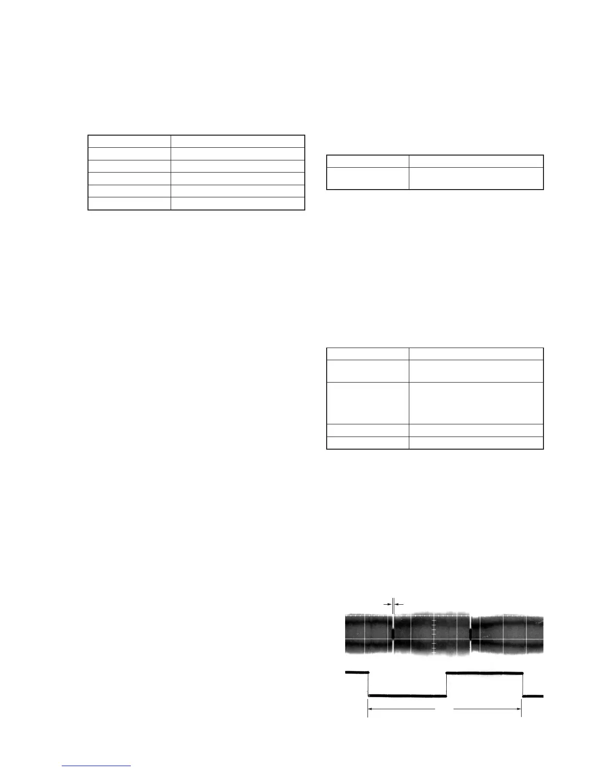
Fig. 6-2-3.
A
2 V
CH1
CH2