6-4
2-5. VIDEO SYSTEM CHECK
2-5-1. Playback Level Check (MA-359 board)
[Adjustment purpose]
Confirm that the playback video signal level is within the
specification.
Mode Playback
Signal Alignment tape: SP mode color bar
portion
Measurement Point CN200 !¡ pin (EEV PB) (Note1)
JW234 (IC001 !• pin : ARCVY)
(Note2)
Measuring Instrument Oscilloscope
Specified Value A=2.00 ± 0.18V
Note 1: For SLV-SF99 model. (Except B model)
Note 2: For SLV-SE85/SF90 or B model.
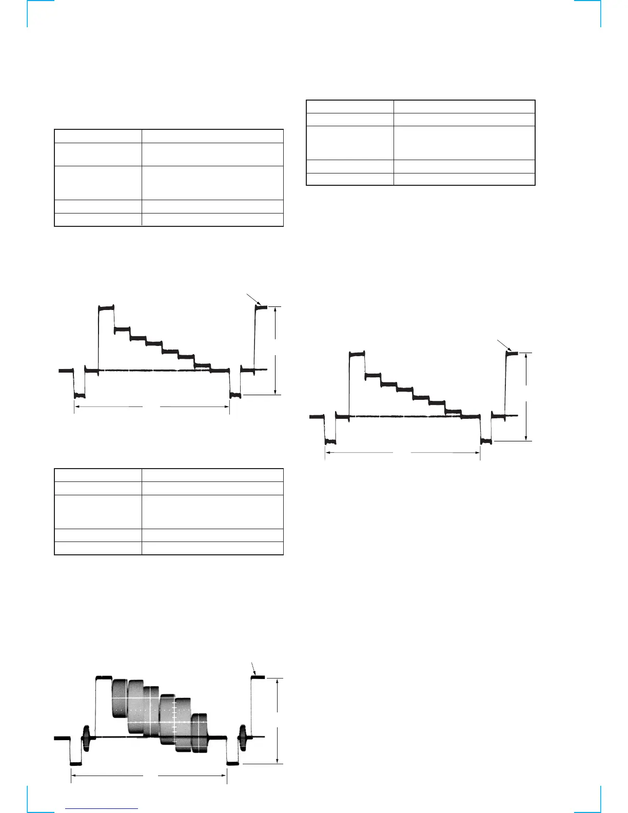
[Check method]
1) Check that the video signal level (A) satisfies the specified
value.
Fig. 6-2-4.
2-5-2. Sync AGC Check (MA-359 board)
[Adjustment purpose]
Confirm that the E-E video output level is within the specification.
Mode E-E
Signal Color bar
Measurement Point CN200 !¡ pin (EEV PB) (Note1)
JW234 (IC001 !• pin : ARCVY)
(Note2)
Measuring Instrument Oscilloscope
Specified Value A=2.0 ± 0.1V
Note 1: For SLV-SF99 model. (Except B model)
Note 2: For SLV-SE85/SF90 or B model.
Switch setting:
INPUT SELECT ........................................L2
[Check method]
1) Input a color bar signal to VIDEO LINE 2 terminal.
2) Check that the video signal level (A) satisfies the specified
value.
Fig. 6-2-7.
2-5-3. Deviation Check (MA-359 board)
[Adjustment purpose]
Confirm that the YFM signal deviation is within the specification.
Mode Recording and playback (SP mode)
Signal Color bar
Measurement Point CN200 !¡ pin (EEV PB) (Note1)
JW234 (IC001 !• pin : ARCVY)
(Note2)
Measuring Instrument Oscilloscope
Specified Value A=2.00 ± 0.18V
Note 1: For SLV-SF99 model. (Except B model)
Note 2: For SLV-SE85/SF90 or B model.
Note 3: This check should be carried out upon completion of “Playback
Level Check” and “Sync AGC Check”.
Switch setting:
INPUT SELECT ................................... L2
[Check method]
1) Record the color bar signal.
2) Playback the recorded section.
3) Check that the video signal level (A) satisfies the specified
value.
Fig. 6-2-6.
White (100%)
A
H
H
A
White (100%)
White (100%)
A
H