9
HDMI terminal
Outputs the image from the camera as an
HD
MI video signal.
Note
Under the following cases, VGA output is
applied to the image output through the
HDMI terminal and the image quality
degrades.
• When the SYSTEM SELECT switch is set to 7
• When you choose [720/59.94p VGA] for
[V
IDEO FORMAT] on the OSD menu
• When you choose [Format] - [1280×720/
5
9.94p (HDMI:VGA)] for [Video Out] on the
Web App menu
• When you perform setup using the OSD
me
nu or Web App, set the SYSTEM SELECT
switch to 6.
SD
I OUT terminal
Outputs the image as an SDI video signal.
When the video format is set to 4K, images
ar
e not output from SDI OUT terminal.
F
an / Exhaust port
Evacuate the heat inside the camera.
Notes
• Do not cover this port to avoid
malfunctions.
• The temperature of the area near this port
may
get high. Be careful.
(earth) terminal
LAN (network) terminal (RJ-45)
Network communication and PoE++(class8)*
po
wer supply are provided using the
network cable (category 5e or higher).
The orange LED lights up when connected by
10
00BASE-T, turns off on other occasions.
The green LED lights up and flashes when
d
ata communication is performed after the
link is established.
* PoE++(class8): Power over Ethernet Plus Plus is
abbreviated. Based on IEEE802.3bt (Type 4
Class8). For details on the connection, refer to the
operating manual of the power supply device.
Note
Do not connect the PoE++(class8) power
supply device and AC adapter at the same
time to avoid heat generation.
Factory settings for network
DHCP: On
Name: A40 (SRG-A40)
A12 (SRG-A12)
User name: admin
Password: blank space
Notes
• Set a password when the camera is being
operated for the first time.
• When connecting this camera to a
ne
twork, connect via a system that
provides a protection function such as a
router or firewall. If connected without
such protection, security issues may occur.
A
C adapter cord clamper mounting hole
Clamping the supplied cord clamper
p
revents the AC adapter from coming out.
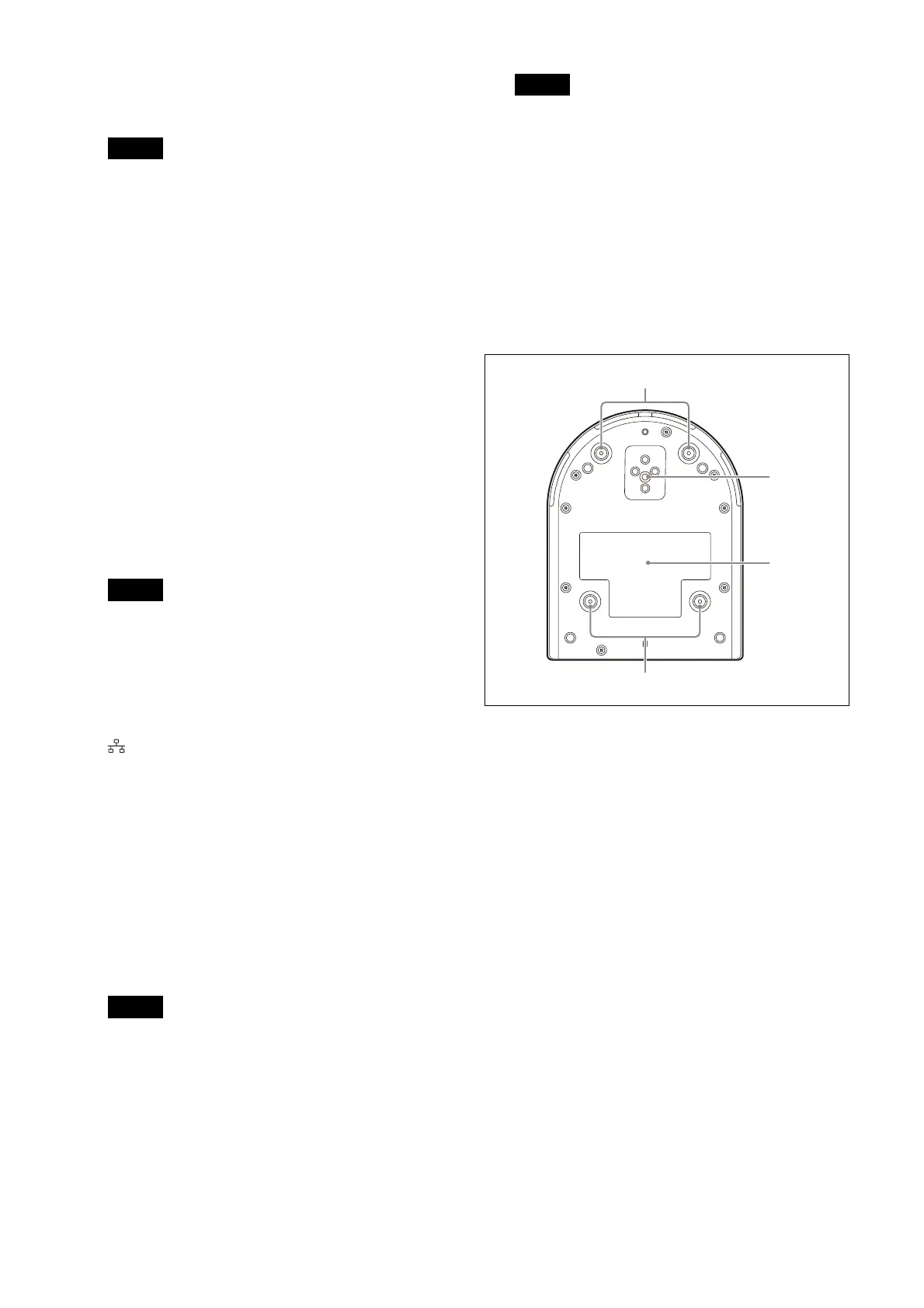
Bottom
C
eiling bracket mounting screw holes
When installing on the ceiling, use the screw
ho
les to attach the supplied ceiling bracket
(A). For details, see “Installing the Camera”
(page 15).
Tr
ipod socket hole
Use this to attach the tripod, etc.
For details, see “Attaching the Camera to a
Tripod” (page 15).