23
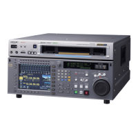
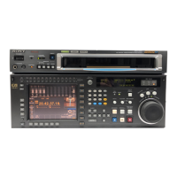
2-1 Control Panel
Chapter 2 Locations and Functions of Parts
Each page can be set so that it is not displayed in the INFO
SELECT menu under the OTHERS CHECK menu in the
MAINTENANCE menu.
For details, refer to the Maintenance Manual Volume 1.
Page 1: System status
SYS: Shows the recording system information (signal
standard and tape format).
PB: Shows the information recorded on the tape (signal
standard and tape format) while being played back.
FC: Shows the converted signal standard when an HKSR-
5001 board is installed.
TC: Shows the LTC/VITC and DF/NDF settings, or the
time code sent to the external monitor.
Page 2: System status
ACTIVE LINE: Shows the status of 1080/1035
conversion active line.
1080t1080
1080t1035(CROP)
1080t1035(CONV)
1035t1035
1035t1080(PANEL)
1035t1080(CONV): Shows the current conversion
status.
- - - - -: Cannot be converted.
OFF: No conversion done.
DOWN CONV. OUTPUT: Shows the output status of the
down converter.
ACTIVE: Output.
MUTING: No output.
EOS: Appears at the location of the time code for the valid
end of the previous recording.
Page 3: Phase (OUTPUT)
HD SDI OUTPUT ADV.: Shows the phase of the main
line HD SDI output.
OFF: In phase with reference.
–90H: 90H (HD) advanced with respect to reference.
DOWN CONV. OUTPUT ADV.: Shows the phase of the
down converter output.
OFF: In phase with reference.
–2H: 2H (SD) advanced with respect to reference.
Page 4: Phase (AUDIO)
AUDIO PB OUTPUT ADV.: Shows the phase of the
audio output signal.
OFF: Output in phase with the video output signal.
–1Frame: Output one frame advanced with respect to
the video output signal.
AUDIO INPUT DELAY: Shows the recording phase of
the audio input signal.
OFF: Recorded in phase with the video output signal.
+1Frame: Recorded one frame delayed with respect to
the video input signal.
AES/EBU & ANA OUTPUT: Shows the phase of the
AES/EBU and ANALOG AUDIO outputs.
REF: Output in phase with reference.
FC: In phase with the FC output.
–90H(HD): 90H (HD) advanced with respect to
reference.
–2H(SD): 2H (SD) advanced with respect to
reference.
Page 5: Phase (TC)
TC INPUT DELAY: Shows the recording phase of the
input time code.
OFF: Recorded in phase with the input video signal.
+1Frame: Recorded one frame delayed with respect to
the input video signal.
LTC OUTPUT: Shows the phase of the output LTC.
LINE: Output in phase with the main line HD SDI
output.
FC: Output in phase with the FC output.
Page 6: Meta Data
The display changes depending on the tape format in use.
• HDCAM-SR
META DATA LINE(REC): Shows the status of the
three lines for metadata recording on this unit.
META DATA LINE(OUT): Shows the status of the
three lines of main HD SDI output into which
metadata is multiplexed.
META DATA LINE(FC): Shows the status of the three
lines of output from the optional HKSR-5001
format converter board into which metadata is
multiplexed.
META DATA LINE(SD): Shows the status of the three
lines of SD SDI output into which metadata is
multiplexed.
• HDCAM
Displays L1/L2/DID/SDID. This combination is
counted as 1 packet. Up to 3 packets can be recorded.
On the SRW-5500, the system settings related to
recording are shown on the left. If data is detected in the
input signal, the L1/L2 values are highlighted. The right
side shows playback values detected on the tape.
Page 7: Select FPS
TAPE FORMAT: Shows the playback format of the tape.
ACTUAL FORMAT: Shows the recording format of the
tape recorded with frames per second (Select FPS
mode) specified.
Select FPS:
Shows the transportation speed and playback
speed of the tape recorded with Select FPS mode
specified.
Page 8: VPID
Shows the VPID
1)
multiplexed with the input signal
for LINK-A and LINK-B.
1) VPID
A packet standard defined by SMPTE-352M that identifies the format of
multiplexed signals on the SDI.